Advertisement
Quick Links
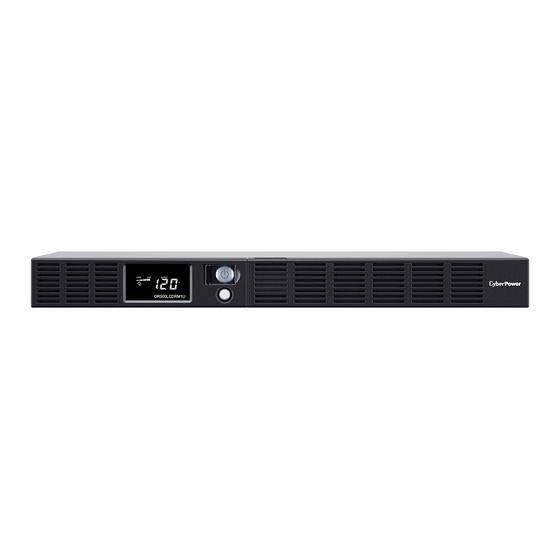
OR500LCDRM1U / OR700LCDRM1U
User's Manual
PRODUCT REGISTRATION
Thank you for purchasing a CyberPower product. Please take a few minutes to register your product at:
www.CyberPowerSystems.com/Registration. Registration certifies your product's warranty, confirms your ownership in the event
of a product loss or theft and entitles you to free technical support. Register your product now to receive the benefits of CyberPower
ownership.
IMPORTANT SAFETY WARNINGS
(SAVE THESE INSTRUCTIONS)
This manual contains important safety instructions. Please read and follow all instructions carefully during installation and operation
of the unit. Read this manual thoroughly before attempting to unpack, install, or operate your UPS.
CAUTION! To prevent the risk of fire or electric shock, install in a temperature and humidity controlled indoor area free of
conductive contaminants. (Please see specifications for acceptable temperature and humidity range).
CAUTION! To reduce the risk of electric shock, do not remove the cover. There are no user serviceable parts inside except for the
battery.
CAUTION! Hazardous live parts inside can be energized by the battery even when the AC input power is disconnected.
CAUTION! The UPS must be connected to an AC power outlet with fuse or circuit breaker protection. Do not plug into an outlet that
is not grounded. If you need to de-energize this equipment, turn off and unplug the unit.
CAUTION! To avoid electric shock, turn off the unit and unplug it from the AC power source before installing a computer
component.
DO NOT USE FOR MEDICAL OR LIFE SUPPORT EQUIPMENT! CyberPower Systems does not sell products for life support or
medical applications. DO NOT use in any circumstance that would affect operation and safety of life support equipment, any medical
applications or patient care.
DO NOT USE WITH OR NEAR AQUARIUMS! To reduce the risk of fire or electric shock, do not use with or near an aquarium.
Condensation from the aquarium can cause the unit to short out.
DO NOT USE THE UPS ON ANY TRANSPORTATION! To reduce the risk of fire or electric shock, do not use the unit on any
transportation such as airplanes or ships. The effect of shock or vibration caused during transit and the damp environment can cause
the unit to short out.
INSTALLING YOUR UPS SYSTEM
UNPACKING
Inspect the UPS upon receipt. The box should contain the following:
(a) UPS unit (b) User's manual (c) Rack mount brackets (d) USB A+B type cable (e) Warranty registration card
*PowerPanel® Business Edition software is available on our website. Please visit
to the Software Section for free download.
OVREVIEW
The OR500LCDRM1U/OR700LCDRM1U provides automatic voltage regulation for inconsistent utility power. The
OR500LCDRM1U / OR700LCDRM1U features 1030 Joules of surge protection, and provides battery backup during power outages.
The OR500LCDRM1U / OR700LCDRM1U ensures consistent power to your computer system and its included software will
automatically save your open files and shutdown your computer system during a utility power loss.
HOW TO DETERMINE THE POWER REQUIREMENTS OF YOUR EQUIPMENT
Ensure that the equipment plugged into the UPS does not exceed the UPS unit's rated capacity. If the rated capacities of the
1.
unit are exceeded, an overload condition may occur and cause the UPS unit to shut down or the circuit breaker to trip.
2.
There are many factors that can affect the amount of power that your electronic equipment will require. For optimal system
performance keep the load below 80% of the unit's rated capacity.
AUTOMATIC VOLTAGE REGULATOR
The OR500LCDRM1U/OR700LCDRM1U stabilizes inconsistent utility power. The incoming utility power may be damaging to
important data files, but with Automatic Voltage Regulation, the computer will not experience damaging voltage levels. An
Automatic Voltage Regulator automatically increases low or decreases high voltage to a consistent, computer safe 110v/120v. The
unit's powerful sealed lead-acid batteries will provide power only if the incoming voltage drops below 90v or increases above 140v.
HARDWARE INSTALLATION GUIDE
1.
Your new UPS may be used immediately upon receipt. However, after receiving a new UPS, to ensure the battery's maximum
charge capacity, it is recommended that you charge the battery for at least 8 hours. Your UPS is equipped with an auto-charge
feature. When the UPS is plugged into an AC outlet, the battery will automatically charge whether the UPS is turned on or
turned off.
2.
If you will use the software, connect the USB cable to the USB port on the UPS.
3.
With the UPS unit turned off and unplugged, connect your computer, monitor, and any other peripherals requiring battery
backup into the battery power supplied outlets. Plug the other peripheral equipment (e.g. printer, scanner, speakers, etc.)
into the full-time surge protection outlets. DO NOT plug a laser printer, paper shredder, copier, space heater, vacuum
cleaner, sump pump, or other large electrical device into the "Battery and Surge Protected Outlets". The power
demands of these devices will overload and possibly damage the unit.
4.
Plug the UPS into a 2 pole, 3 wire grounded receptacle (wall outlet). Make sure the wall
branch outlet is protected by a fuse or circuit breaker and does not service equipment
with large electrical demands (e.g. air conditioner, refrigerator, copier, etc.). The warranty
prohibits the use of extension cords, outlet strips, and surge strips in conjunction with the
UPS unit.
Press the power switch to turn the unit on. The Power On indicator light will illuminate green and the unit will "beep" twice.
5.
6.
If an overload is detected, an audible alarm will sound and the unit will emit one long beep. To correct this, turn the UPS off
and unplug at least one piece of equipment from the battery power supplied outlets. Make sure the circuit breaker is
depressed and then turn the UPS on.
7.
To maintain optimal battery charge, leave the UPS plugged into an AC outlet at all times.
8.
To store the UPS for an extended period of time, cover it and store with the battery fully charged. While in storage, recharge
the battery every three months to ensure optimal battery life.
9.
Ensure the wall outlet and UPS are located near the equipment being attached for proper accessibility.
BASIC OPERATION
DESCRIPTION
1.
LCD module display
LCD shows all the UPS information with
icons and messages.
2.
Power On Indicator
This LED is illuminated when the utility
condition is normal and the UPS outlets are
providing power, free of surges and spikes.
3.
Power Switch
Master on/off switch for equipment connected to the battery power supplied outlets.
4.
LCD function selected switch
The switch can be used to select the LCD display contents Including input/output voltage and estimated run time, etc.
5.
Battery and Surge Protected Outlets
The unit has four battery powered/surge suppression outlets for connected equipment to ensure temporary uninterrupted operation of
your equipment during a power failure. (DO NOT plug a laser printer, paper shredder, copier, space heater, vacuum cleaner, sump pump
or other large electrical devices into the "Battery and Surge Protected Outlets". The power demands of these devices may overload and
damage the unit.)
6.
Full-Time Surge Protection Outlets
K01-0000786-00
www.CyberPowerSystems.com
1
2
3
4
5
7
8
9
6
The unit has two surge suppression outlets.
7.
Communication Protection Ports RJ45
Communication protection ports, bi-directional, will protect a 10/100/1000Ethernet connection. (RJ45).
8.
USB Port to PC
This port allows connection and communication from the USB port on the computer to the UPS unit. The UPS communicates its status to
the PowerPanel® Business Edition software.
9.
Dry contact
This port produces information for equipment that can read dry contact signals.
10. Circuit Breaker
Located on the back of the UPS, the circuit breaker serves to provide overload and fault protection. Under normal operating conditions,
the circuit breaker is depressed.
11. Electrical Wiring Fault Indicator (Red)
This LED indicator will illuminate to warn the user that a wiring problem exists, such as bad ground, missed ground or reversed wiring. If
this is illuminated, disconnect all electrical equipment from the outlet and have an electrician check to ensure the outlet is properly wired.
The unit will not provide surge protection without being plugged into a grounded and properly wired wall outlet.
12. AC Input
Connect the AC Power cord to a properly wired and grounded outlet.
13. SNMP/HTTP Network Slot
Remove the cover panel to install an optional RMCARD provides remote monitoring and management of your UPS over a network.
REPLACING THE BATTERY
CAUTION! Read and follow the IMPORTANT SAFETY INSTRUCTIONS before servicing the battery.
Service the battery under the supervision of personnel knowledgeable of batteries and their precautions.
CAUTION! Use only the specified type of battery. See your dealer for replacement batteries.
CAUTION! The battery may present the risk of electrical shock. Do not dispose of batteries in a fire, as they may explode. Follow
all local ordinances regarding proper disposal of batteries.
CAUTION! Do not open or mutilate the batteries. Released electrolyte is harmful to the skin and eyes and may be toxic.
CAUTION! A battery can present a high risk of short circuit current and electrical shock. Take the following precautions before
replacing the battery:
1. Remove all watches, rings or other metal objects.
2. Only use tools with insulated handles.
3. DO NOT lay tools or other metal parts on top of battery or any battery terminals.
4. Wear rubber gloves and boots.
5. Determine if the battery is inadvertently grounded. If inadvertently grounded, remove source of ground. CONTACT WITH A
GROUNDED BATTERY CAN RESULT IN ELECTRICAL SHOCK! The likelihood of such shock will be reduced if such grounds
are removed during installation and maintenance (applicable to a UPS and a remote battery supply not having a grounded
circuit).
BATTERY REPLACEMENT PROCEDURE:
1
and go
1. Remove the right-side of the faceplate.
4
4. Remove the retaining screw of the cable
connectors.
DEFINITIONS FOR ILLUMINATED LCD
INDICATORS
Line mode
Select SW
Press
Initial
V
1st
V
2nd
V
3rd
V
4th
V
5th(Return)
V
Press >3sec
V
(Sound Disable)
Press >3sec
Again
V
(Sound Enable)
(Overload)
V
"V" : Illuminated, "X" : Not Illuminated, "--" : Either
Battery mode
Select SW
Press
Initial
X
1st
X
2nd
X
3rd
X
4th
X
10
11
12
5th(Return)
X
Press >3sec
X
(Sound Disable)
Press >3sec
again(Sound
X
Enable)
(Overload)
X
"V" : Illuminated, "X" : Not Illuminated, "--" : Either
2
2. Remove the three retaining screws on
the cable protection cover then remove
the cover.
5
UPS Status Display
Capacity Display
Load
Battery
Cap.
Cap.
X
--
X
V
X
X
--
X
V
X
X
--
X
V
X
X
--
X
X
V
X
--
X
V
X
X
--
X
V
X
X
V
X
--
--
X
X
X
--
--
X
--
V
--
--
UPS Status Display
Capacity Display
Load
Battery
Cap.
Cap.
Voltage
V
--
X
X
V
V
--
X
X
V
V
--
X
V
X
V
--
X
X
V
V
--
X
X
V
V
--
X
X
V
V
V
X
--
--
V
X
X
--
--
V
--
V
--
--
3
3. Disconnect the black and red
cable.
5. Replace the new battery pack. Assemble
the screws, cover, cable and front panel in
the reverse sequence of above steps.
Recharge the unit for 8 hours to ensure
the UPS performs expected runtime.
Digital Value Display
Input
Output
Run
% of
% of
Voltage
Voltage
Time
Load
Batt.
V
V
V
V
V
V
--
--
--
--
--
--
--
--
--
--
--
--
--
--
--
Digital Value Display
Input
Output
Run
% of
% of
Voltage
Time
Load
Batt.
V
V
V
V
V
V
--
--
--
--
--
--
--
--
--
--
--
--
--
--
--
Advertisement

Related Manuals for CyberPower OR500LCDRM1U


Summary of Contents for CyberPower OR500LCDRM1U
- Page 1 This LED indicator will illuminate to warn the user that a wiring problem exists, such as bad ground, missed ground or reversed wiring. If of a product loss or theft and entitles you to free technical support. Register your product now to receive the benefits of CyberPower this is illuminated, disconnect all electrical equipment from the outlet and have an electrician check to ensure the outlet is properly wired.
- Page 2 If the CPS Product is defective in material or workmanship, CyberPower will repair or replace it at CyberPower’s expense, or, if On-Battery Output Voltage 120Vac +/- 5% CyberPower is unable to or decides not to repair or replace the CPS Product (if defective) within a reasonable time, CyberPower will On-Battery Output Wave Form Simulated Sine Wave refund to you the full purchase price you paid for the CPS Product (purchase receipt showing price paid is required).