Table of Contents
Advertisement
Quick Links
Advertisement
Chapters
Table of Contents

Related Manuals for Novexx Rewinder 2000

Summary of Contents for Novexx Rewinder 2000
- Page 1 SERVICE MANUAL Rewinder 2000 Option Edition 2 - 2/2017...
-
Page 2: Table Of Contents
06/15 Rev. 6.01-01 All devices Using the Documentation Copyright ............2 Text appearance ........10 Documentation structure ........ 3 Title page ..........11 Datapool, documentation object ....3 Abbreviations ..........12 Documentation concept......3 Printer names..........12 Documentation format ........ 6 Parameters ..........12 Printing the documentation ......7 Index .............13 Navigation aids .......... -
Page 3: Copyright
/Using the Documentation All devices Copyright © 2015 by Novexx Solutions GmbH. All rights reserved. Reprinting and reproduction of these documents, including extracts, is only allowed with the express permission of the manufacturer. More detailed information is available from your supplier. -
Page 4: Documentation Structure
06/15 Rev. 6.01-01 USER + SERVICE MANUAL /Using the Documentation All devices Documentation structure Datapool, documentation object The overall documentation is a part of the datapool, which is provided for the printer user and the service personnel on CD or other electronic media. Datapool This datapool includes: –... - Page 5 06/15 Rev. 6.01-01 USER + SERVICE MANUAL /Using the Documentation All devices Subject section Thematically-related subject contents are described in each topic section. A topic section is the smallest unit of information with its own – page numbering, – header bar, –...
- Page 6 64-06 Dispenser Commissioning and Operation 64-08 64-08 Dispenser Setup USER MANUAL Release 1 - 06/2015 Advanced Applications © 2015, Novexx Solutions GmbH, Ohmstraße 3, 85386 Eching, Germany. Maintenance and Cleaning Topic All rights reserved. sections Info-Printouts and Parameters Copyright Symbols...
-
Page 7: Documentation Format
06/15 Rev. 6.01-01 USER + SERVICE MANUAL /Using the Documentation All devices Start page The start page is also only an organisational component and is displayed when the CD starts, or on the Internet on the link to the printer datapool. The following features characterize a start page: –... -
Page 8: Printing The Documentation
06/15 Rev. 6.01-01 USER + SERVICE MANUAL /Using the Documentation All devices Printing the documentation In order to make the documentation readable without a PC, the documents can be printed in A4 as well as in Letter format. For printing, the Acrobat Reader uses the print capabilities of the platform it is run on. -
Page 9: Navigation Aids
06/15 Rev. 6.01-01 USER + SERVICE MANUAL /Using the Documentation All devices Navigation aids Info search The following options are available for quickly searching for information in the paper documentation: – The title page of each manual with a list of contents of the topic section –... -
Page 10: Symbols And Note Signs
06/15 Rev. 6.01-01 USER + SERVICE MANUAL /Using the Documentation All devices Symbols and note signs Warning notes Warning notes warn of a possibly dangerous situation. Personal injury, material damage or data loss are possible, if care is not taken. Depending on the dimension of possible damages, the warning notes look different: •... -
Page 11: Symbols
06/15 Rev. 6.01-01 USER + SERVICE MANUAL /Using the Documentation All devices Symbols Warning of the risk of injury due to moving or rapidly rotating parts! Long hair, loose jewellery, long sleeves, etc.are not admissible when operating the machine. Wear sufficient personal protection gear. Tools required for the described service action. -
Page 12: Title Page
06/15 Rev. 6.01-01 USER + SERVICE MANUAL /Using the Documentation All devices Title page Link Black text in the blue frame: link to topic sections which occur several times in different manuals (click). Link Purple text in the blue frame: link to a topic section which only occurs once and belongs specifically to the manual (click). -
Page 13: Abbreviations
06/15 Rev. 6.01-01 USER + SERVICE MANUAL /Using the Documentation All devices Abbreviations Printer names If there is not enough space to call all printers by their full names, the abbreviated spellings listed in Tab. 2 are used. Spelling Meaning Example, note 64-04/05 64-04, 64-05... -
Page 14: Index
06/15 Rev. 6.01-01 USER + SERVICE MANUAL /Using the Documentation All devices Index Abbreviations ..........12 Link page ............ 5 Alterations, technical ........2 Paper documentation ........7 Copy ............2 Patents ............2 Copyright ............. 2 Pinch Point ..........10 Datapool ............ -
Page 15: Index
06/15 Rev. 6.01-01 OPERATOR / SERVICE MANUAL All printers / print dispensers Safety Notes Note about printer names ......2 Information and qualifications ....... 3 Follow the instructions ....... 3 Information must be made available ..3 Ensure necessary qualifications ....3 Machine operating safety ...... - Page 16 The protective measures described in the following count for all printers (e. g. 64-xx), print-and-apply machines (e. g. ALX 92x) and print-and-apply modules (DPM) distributed by Novexx Solutions. In this document, all above mentioned printer types are referred to as „machine“.
- Page 17 06/15 Rev. 6.01-01 OPERATOR / SERVICE MANUAL Safety Notes All printers / print dispensers Information and qualifications Follow the instructions Safe and efficient operation of the printer can only be guaranteed if you observe all nec- essary information. Product liability and warranty can only be claimed, if the printer was operated according to the notes and instructions in the user manual.
- Page 18 06/15 Rev. 6.01-01 OPERATOR / SERVICE MANUAL Safety Notes All printers / print dispensers Machine operating safety Conditions for safe use Only use the machine in enclosed areas with environmental conditions matching the values given in the technical specifications. ...
- Page 19 02/17 Rev. 02 SERVICE MANUAL Rewinder 2000 Attachment, Setup, Service General Notes ..........2 Setting the sensor current ......17 Intended Purpose ........2 Adjusting the sensor .........18 Properties ........... 2 Inserting material ..........19 System requirements ........3 Starting / Stopping ........21 Printer type ..........
-
Page 20: General Notes
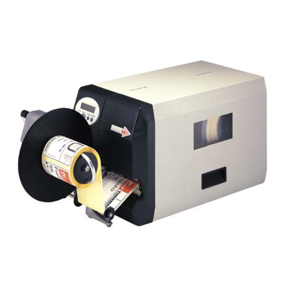
General Notes Intended Purpose The option “Rewinder 2000” (subsequently referred to as the rewinder) is a peripheral device for label printers of the types TTK, TTX 350, 64-xx, AP 5.x, AP 7.t and XLP 50x. The device is designed for winding up label material after it has been printed using one of the printer types named above. -
Page 21: System Requirements
02/17 Rev. 02 SERVICE MANUAL Attachment, Setup, Service Rewinder 2000 System requirements Printer type The rewinder can be operated with the following printer types: • TTX 350 • • 64-xx • AP 5.x • AP 7.t • XLP 50x Preparation for peripheral devices For using the printers with a rewinder, they must be especially equipped (see Tab. -
Page 22: Attaching The Rewinder
02/17 Rev. 02 SERVICE MANUAL Attachment, Setup, Service Rewinder 2000 Attaching the rewinder Before beginning service work, switch off the printer and pull out the mains power supply plug! Under no circumstances should you use the dancer arm as a carrying handle! A... -
Page 23: General Information About Setting Up The Printer
02/17 Rev. 02 SERVICE MANUAL Attachment, Setup, Service Rewinder 2000 General information about setting up the printer After mounting the rewinder you must set up the printer for operation with the new peripheral device. This is done by selecting the appropriate parameter in the parameter menu of the printer. -
Page 24: Rotation Speed With 64-Xx / Ap 5.X / Ap 7.T / Xlp 50X
02/17 Rev. 02 SERVICE MANUAL Attachment, Setup, Service Rewinder 2000 Rotation speed with 64-xx / AP 5.x / AP 7.t / XLP 50x With those printer types, the rewinder rotation speed depends on the print speed. A low print speed leads to a slower rewinder rotation as a high print speed. -
Page 25: Setting Up Ttx 350 / Ttk
02/17 Rev. 02 SERVICE MANUAL Attachment, Setup, Service Rewinder 2000 Setting up TTX 350 / TTK Setup the printer for rewinder-use by performing the three subsequently described steps: Activating the rewinder / Selecting the Rotation Direction on page 7. Setting the sensor current... -
Page 26: Setting The Sensor Current
02/17 Rev. 02 SERVICE MANUAL Attachment, Setup, Service Rewinder 2000 Setting the sensor current Befor using the rewinder for the first time, the sensor current must be set by a potentiometer at the rewinder [1]. Rewinder (section) Turn counter-clockwise =>... -
Page 27: Adjusting The Sensor
02/17 Rev. 02 SERVICE MANUAL Attachment, Setup, Service Rewinder 2000 Adjusting the sensor The dancer arm controls the winding speed of the rewinder by means of a sensor. Bevor applying the rewinder for the first time, the dancer arm has to be brought in both end positions to adjust the sensor. -
Page 28: Setting Up Ap 7.T
02/17 Rev. 02 SERVICE MANUAL Attachment, Setup, Service Rewinder 2000 Setting up AP 7.t Setup the printer for rewinder-use by performing the following steps: Activating the rewinder on page 10. Selecting the direction of rotation on page 10. Setting the sensor current on page 11. -
Page 29: Setting The Sensor Current
02/17 Rev. 02 SERVICE MANUAL Attachment, Setup, Service Rewinder 2000 Setting the sensor current Befor using the rewinder for the first time, the sensor current must be set by a potentiometer at the rewinder [3]. Rewinder (section) Turn counter-clockwise =>... -
Page 30: Adjusting The Sensor
02/17 Rev. 02 SERVICE MANUAL Attachment, Setup, Service Rewinder 2000 Adjusting the sensor The dancer arm controls the winding speed of the rewinder by means of a sensor. Bevor applying the rewinder for the first time, the dancer arm has to be brought in both end positions to adjust the sensor. -
Page 31: Setting Up 64-Xx / Ap 5.X
02/17 Rev. 02 SERVICE MANUAL Attachment, Setup, Service Rewinder 2000 Setting up 64-xx / AP 5.x Setup the printer for rewinder-use by performing the following steps: Activating the rewinder on page 13. Selecting the direction of rotation on page 13. -
Page 32: Setting The Sensor Current
02/17 Rev. 02 SERVICE MANUAL Attachment, Setup, Service Rewinder 2000 Setting the sensor current Befor using the rewinder for the first time, the sensor current must be set by a potentiometer at the rewinder [3]. Rewinder (section) Turn counter-clockwise =>... -
Page 33: Adjusting The Sensor
02/17 Rev. 02 SERVICE MANUAL Attachment, Setup, Service Rewinder 2000 Adjusting the sensor The dancer arm controls the winding speed of the rewinder by means of a sensor. Bevor applying the rewinder for the first time, the dancer arm has to be brought in both end positions to adjust the sensor. -
Page 34: Setting Up Xlp 50X
02/17 Rev. 02 SERVICE MANUAL Attachment, Setup, Service Rewinder 2000 Setting up XLP 50x Setup the printer for rewinder-use by performing the following steps: Activating the rewinder on page 16. Reversing the direction of rotation on page 16. Setting the sensor current on page 17. -
Page 35: Setting The Sensor Current
02/17 Rev. 02 SERVICE MANUAL Attachment, Setup, Service Rewinder 2000 Setting the sensor current Befor using the rewinder for the first time, the sensor current must be set by a potentiometer at the rewinder [3]. Rewinder (section) Turn counter-clockwise =>... -
Page 36: Adjusting The Sensor
02/17 Rev. 02 SERVICE MANUAL Attachment, Setup, Service Rewinder 2000 Adjusting the sensor The dancer arm controls the winding speed of the rewinder by means of a sensor. Bevor applying the rewinder for the first time, the dancer arm has to be brought in both end positions to adjust the sensor. -
Page 37: Inserting Material
02/17 Rev. 02 SERVICE MANUAL Attachment, Setup, Service Rewinder 2000 Inserting material Direction of rotation The material – depending on the set direction of rotation – is wound around the core in a clockwise or anti-clockwise direction [9]. Left side: direction of rotation = left (labels outside); right side: direction of rotation =... - Page 38 02/17 Rev. 02 SERVICE MANUAL Attachment, Setup, Service Rewinder 2000 3. Remount the guide disk. The recesses at the inner diameter of the guide disk (arrows) must be positioned over the clamping bar legs (5). 4. Push the guide disk up to the material edge (6).
-
Page 39: Starting / Stopping
02/17 Rev. 02 SERVICE MANUAL Attachment, Setup, Service Rewinder 2000 Starting / Stopping After securing the material end, proceed as follows to start printer and rewinder: The printer is set to offline mode (respectively “Home”-screen for XLP 50x). TTX 350 / TTK Starting 1. -
Page 40: Xlp 50X
02/17 Rev. 02 SERVICE MANUAL Attachment, Setup, Service Rewinder 2000 Rotation speed Pressing the Cut button after securing the material end lets the rewinder start winding at a comparably slow, constant speed. This startup speed is independent of the formerly set printspeed and is maintained until the dancer arm reaches its final position for the first time after starting. -
Page 41: Servicing The Rewinder
02/17 Rev. 02 SERVICE MANUAL Attachment, Setup, Service Rewinder 2000 Servicing the Rewinder General notes Before beginning service work, switch off the printer and pull out the mains plug. Detach the rewinder from the printer before taking the following steps. -
Page 42: (Ttx 350 / Ttk) Setting The Output Stage
02/17 Rev. 02 SERVICE MANUAL Attachment, Setup, Service Rewinder 2000 [10] Setting of the shortcut current on boards of the older type (recognizable by the two potentiometers). (TTX 350 / TTK) Setting the output stage The peripherals board used in TTX 350 and TTK must be set to a short- circuit current of 30 mA [11]. -
Page 43: Rewinder Core
02/17 Rev. 02 SERVICE MANUAL Attachment, Setup, Service Rewinder 2000 Rewinder core The rewinder core is available in diameters of 1.5", 3" and 4". The rewinder core can be replaced with another diameter. To do this, proceed as follows: Disassembling/assembly 1. -
Page 44: Buffer Disc
02/17 Rev. 02 SERVICE MANUAL Attachment, Setup, Service Rewinder 2000 Buffer disc The buffer disc (1) guides the label material while it is being wound up. A ratchet wheel is fitted to the back of the buffer disc, over which the drive belt runs. -
Page 45: Toothed Belt
02/17 Rev. 02 SERVICE MANUAL Attachment, Setup, Service Rewinder 2000 Assembly 1. Lay the belt around the motor sprocket (1) and belt tensioner (2). 2. Slowly tighten the buffer disc just like tightening a chain. Hold the belt in position with a screwdriver. -
Page 46: Cable Harness / Light Barrier
02/17 Rev. 02 SERVICE MANUAL Attachment, Setup, Service Rewinder 2000 Cable harness / light barrier The light barrier (transparency), in conjunction with the light barrier wedge, controls the position of the dancer arm. More or less light is allowed to pass through the light barrier wedge depending on the position of the dancer arm. -
Page 47: Light Barrier Wedge
02/17 Rev. 02 SERVICE MANUAL Attachment, Setup, Service Rewinder 2000 Light barrier wedge Tool – Screwdriver, small Disassembling/assembly 1. Disassembling the light barrier. More detailed information can be found in the section Cable harness / light barrier. 2. Remove the retaining ring and light barrier wedge (1). -
Page 48: Technical Specifications
02/17 Rev. 02 SERVICE MANUAL Attachment, Setup, Service Rewinder 2000 Technical Specifications Motor Stepper motor Position sampling Infrared light barrier Rot. direction Free selectable – Rewind direction with label facing outside or inside. Rewind speed Max. 203 mm/s (8"/s) Spezification Max. -
Page 49: Troubleshooting
02/17 Rev. 02 SERVICE MANUAL Attachment, Setup, Service Rewinder 2000 Troubleshooting General The status reports should be printed and evaluated to check the mechanical and electronic functional capability if no obvious defects are evident. Information about the status reports can be found in the chapter "Info Printouts and Parameters". -
Page 50: Appendix
02/17 Rev. 02 SERVICE MANUAL Attachment, Setup, Service Rewinder 2000 Appendix Pin assignment light barrier board Rewinder Connection D-sub 15 light sensor board plug (3 pin) (Light barrier) Light barrier board cable harness (inside of the rewinder) [12] Pin assignment between the light barrier board and rewinder cable harness... -
Page 51: (Ap 5.X / Xlp 50X) Run-In Roller For Narrow Labels
02/17 Rev. 02 SERVICE MANUAL Attachment, Setup, Service Rewinder 2000 (AP 5.x / XLP 50x) Run-in roller for narrow labels To improve the guiding accuracy of AP 5.x/XLP 50x printers processing very narrow label material, it is recommended to install an additional run-in roller (1) (article number A100422). -
Page 52: Index
02/17 Rev. 02 SERVICE MANUAL Attachment, Setup, Service Rewinder 2000 Index – TTX 350 ..........24 Application ........... 2 Assembly, rewinder ........4 Pin assignment light barrier board .... 32 properties ............ 2 Belt tensioner ..........27 Bouncer arm ..........29 Rewinder core ........... - Page 53 02/17 Rev. 02 SERVICE-HANDBUCH / SERVICE MANUAL Rewinder 2000 Ersatzteilliste / Spare Parts List Gehäuse / Housing ........2 Antrieb / Drive unit ......... 6 Tänzerarm / Bouncer arm ......3 Kabelbaum + Lichtschranke / Cable harness + Light barrier ......7 Rewinder-Kern / Rewind mandrel (1) .....
- Page 54 02/17 Rev. 02 SERVICE-HANDBUCH / SERVICE MANUAL Ersatzteilliste / Spare Parts List Rewinder 2000 Gehäuse / Housing ID Bezeichnung Designation Teilenr. / Part no. Grundplatte Rewinder 450 ZSB Base plate assy. A1990 (4") A1991 (5") A1992 (6") Abdeckplatte f. Rewinder 64-xx...
- Page 55 02/17 Rev. 02 SERVICE-HANDBUCH / SERVICE MANUAL Ersatzteilliste / Spare Parts List Rewinder 2000 Tänzerarm / Dancer arm ID Bezeichnung Designation Teilenr. / Part no. Tänzer Rewinder ZSB Dancer rewinder ass. 99043 (64-04 / TTX 350 / TTK / AP 5.4 / XLP 504) 99086 (64-05) 99108 (64-06 / AP 5.6 / XLP 506)
- Page 56 02/17 Rev. 02 SERVICE-HANDBUCH / SERVICE MANUAL Ersatzteilliste / Spare Parts List Rewinder 2000 Rewinder-Kern / Rewind mandrel (1) ID Bezeichnung Designation Teilenr. / Part no. Scheibe Rewinder ZSB Disk rewinder ass. A0035 A0326 (64-04 / TTX 350 / TTK / Option 1.5 Zoll Kern ZSB...
- Page 57 02/17 Rev. 02 SERVICE-HANDBUCH / SERVICE MANUAL Ersatzteilliste / Spare Parts List Rewinder 2000 Rewinder-Kern / Rewind mandrel (2) ID Bezeichnung Designation Teilenr. / Part no. Klemmbügel 1,5“ Clamp strap 1.5 inch A0323 (64-04 / TTX 350 / TTK / AP 5.4 / XLP 504)
- Page 58 02/17 Rev. 02 SERVICE-HANDBUCH / SERVICE MANUAL Ersatzteilliste / Spare Parts List Rewinder 2000 Antrieb / Drive unit ID Bezeichnung Designation Teilenr. / Part no. Rewindermotor 64-xx ZSB Rewinder motor ass. A8652 Zahnriemen HTD 384-3M-06 Toothed belt 99075 Exzenterachse Eccentric axle...
- Page 59 02/17 Rev. 02 SERVICE-HANDBUCH / SERVICE MANUAL Ersatzteilliste / Spare Parts List Rewinder 2000 Kabelbaum + Lichtschranke / Cable harness + Light barrier ID Bezeichnung Designation Teilenr. / Part no. Kabelbaum Cable harness A2311 Lichtschrankenkeil Light barrier wedge 99018 Abstandsfeder...
Need help?
Do you have a question about the Rewinder 2000 and is the answer not in the manual?
Questions and answers