
Summary of Contents for Aprotech GOLUB 45 Series
- Page 1 Industrial Panel- and Box-PCs GOLUB 45xx AMD Ryzen™ V1605B fanless Box-PC with intigrated TPM module USER´S MANUAL...
-
Page 2: Table Of Contents
2.3.2 COM 1 Port ............................30 2.3.3 COM Port (COM2/ COM3/ COM4) ................... 31 2.3.4 4-Pole 3.5mm Microphone-in/ Speaker-out Jack ............. 32 2.3.5 SMA Antenna Opening ....................... 33 APROTECH GmbH Trade register: Rathsbergstrasse 17 Nuremberg HRB 23727 phone: +49 911 / 65 00 79-50 eMail: info@aprotech.de... - Page 3 4.13 Position New Boot Device ........................84 4.14 Watchdog Timer ............................85 Chapter 5 OS Support and Driver Installation 5.1 Operating System Compatibility ......................86 APROTECH GmbH Trade register: Rathsbergstrasse 17 Nuremberg HRB 23727 phone: +49 911 / 65 00 79-50 eMail: info@aprotech.de...
- Page 4 Appendix B PoE On/ Off Control PoE On/ Off Control Function Reference ....................103 GetStatusPoEPort ........................... 103 EnablePoEPort ............................104 DisablePoEPort ............................105 APROTECH GmbH Trade register: Rathsbergstrasse 17 Nuremberg HRB 23727 phone: +49 911 / 65 00 79-50 eMail: info@aprotech.de...
-
Page 5: Legal Information
For questions in regards to hardware/ software compatibility, customers should contact APROtech GmbH sales representative or technical support. To the extent permitted by applicable laws, APROtech GmbH shall NOT be responsible for any interoperability or compatibility issues that may arise when (1) products, software, or options not certified and supported;... -
Page 6: Copyright Notice
This manual is intended to be used as an informative guide only and is subject to change without prior notice. It does not represent commitment from APROtech GmbH. APROtech GmbH shall not be liable for any direct, indirect, special, incidental, or consequential damages arising from the use of the product or documentation, nor for any infringement on third party rights. -
Page 7: Safety Precautions
Avoid dust, debris, carpets, plastic, vinyl and styrofoam in your work area. Do not remove any module or component from its anti-static bag before installation APROTECH GmbH Trade register: Rathsbergstrasse 17 Nuremberg HRB 23727 phone: +49 911 / 65 00 79-50 eMail: info@aprotech.de... -
Page 8: About This Manual
AMD Ryzen™ Embedded V1000 4-core/ 8-thread processor. The manual also demonstrates the system’s general installation procedures. Revision History Version Date Description Oct. 2019 Initial release APROTECH GmbH Trade register: Rathsbergstrasse 17 Nuremberg HRB 23727 phone: +49 911 / 65 00 79-50 eMail: info@aprotech.de Managing Director: 90411 Nuremberg / Germany USt.-Id-No.: DE 256 058 089... -
Page 9: Chapter 1 Introduction
GOLUB 45xx series is available in two CPU variants, the V1807B (45W) variant is for high compu- ting power demand and the V1605B (15W) variant is designed for rugged fanless operation. APROTECH GmbH Trade register: Rathsbergstrasse 17... -
Page 10: Specification Of Golub 4515
Operating -25°C ~ 70°C* temperature Storage -40°C ~85°C temperature Humidity 10%~90% , non-condensing APROTECH GmbH Trade register: Rathsbergstrasse 17 Nuremberg HRB 23727 phone: +49 911 / 65 00 79-50 eMail: info@aprotech.de Managing Director: 90411 Nuremberg / Germany USt.-Id-No.: DE 256 058 089... - Page 11 Operating, MIL-STD -810G, Method 516.6, Procedure I, Table 516.6 -II CE/ FCC Class A, according to EN 55032 & EN 55024 * For sub-zero and over 60°C operating temperature, a wide temperature HDD or Solid State Disk (SSD) is required. APROTECH GmbH Trade register: Rathsbergstrasse 17...
-
Page 12: Specification Of Golub 4545
External -accessible 80mm x 80mm fan for system heat dissipation Environmental Operating -25°C ~ 70°C*/** temperature Storage -40°C ~85°C temperature APROTECH GmbH Trade register: Rathsbergstrasse 17 Nuremberg HRB 23727 phone: +49 911 / 65 00 79-50 eMail: info@aprotech.de Managing Director: 90411 Nuremberg / Germany USt.-Id-No.: DE 256 058 089... - Page 13 CE/ FCC Class A, according to EN 55032 & EN 55024 * For sub-zero and over 60°C operating temperature, a wide temperature HDD or Solid State Disk (SSD) is required. ** Operating temperature is up to 70°C only if the external-accessible fan is installed. APROTECH GmbH Trade register: Rathsbergstrasse 17...
-
Page 14: Front Panel View
Industrial Panel- and Box-PCs 1.3 Dimension of GOLUB 4515 NOTE: All measurements are in millimeters (mm). 1.3.1 Front Panel View APROTECH GmbH Trade register: Rathsbergstrasse 17 Nuremberg HRB 23727 phone: +49 911 / 65 00 79-50 eMail: info@aprotech.de Managing Director: 90411 Nuremberg / Germany USt.-Id-No.: DE 256 058 089... -
Page 15: Dio Panel View
Industrial Panel- and Box-PCs 1.3.2 DIO Panel View 1.3.3 COM and Audio Port Panel View APROTECH GmbH Trade register: Rathsbergstrasse 17 Nuremberg HRB 23727 phone: +49 911 / 65 00 79-50 eMail: info@aprotech.de Managing Director: 90411 Nuremberg / Germany USt.-Id-No.: DE 256 058 089... -
Page 16: Bottom View
Industrial Panel- and Box-PCs 1.3.4 Bottom View APROTECH GmbH Trade register: Rathsbergstrasse 17 Nuremberg HRB 23727 phone: +49 911 / 65 00 79-50 eMail: info@aprotech.de Managing Director: 90411 Nuremberg / Germany USt.-Id-No.: DE 256 058 089 fax: +49 911 / 65 00 79-79 Web: www.aprotech.de... -
Page 17: Dimension Of Golub 4515
Industrial Panel- and Box-PCs 1.4 Dimension of GOLUB 4545 NOTE: All measurements are in millimeters (mm). 1.4.1 Front Panel View APROTECH GmbH Trade register: Rathsbergstrasse 17 Nuremberg HRB 23727 phone: +49 911 / 65 00 79-50 eMail: info@aprotech.de Managing Director: 90411 Nuremberg / Germany USt.-Id-No.: DE 256 058 089... -
Page 18: Dio Panel View
Industrial Panel- and Box-PCs 1.4.2 DIO Panel View 1.4.3 COM and Audio Port Panel View APROTECH GmbH Trade register: Rathsbergstrasse 17 Nuremberg HRB 23727 phone: +49 911 / 65 00 79-50 eMail: info@aprotech.de Managing Director: 90411 Nuremberg / Germany USt.-Id-No.: DE 256 058 089... -
Page 19: Bottom View
Industrial Panel- and Box-PCs 1.4.4 Bottom View APROTECH GmbH Trade register: Rathsbergstrasse 17 Nuremberg HRB 23727 phone: +49 911 / 65 00 79-50 eMail: info@aprotech.de Managing Director: 90411 Nuremberg / Germany USt.-Id-No.: DE 256 058 089 fax: +49 911 / 65 00 79-79 Web: www.aprotech.de... -
Page 20: Chapter 2 System Overview
When you receive the package of GOLUB 45xx series, please check immediately if the package contains all the items listed in the following table. If any item is missing or damaged, please contact APROtech GmbH for further assistance. Item Description... -
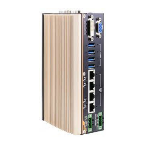
Page 21: Golub 45Xx Front Panel
The DisplayPort is a high-resolution graphics output DisplayPort output supporting up to 4096 x 2160 @ 30Hz. VGA port output VGA output supports resolution up to 1920x1200@60Hz APROTECH GmbH Trade register: Rathsbergstrasse 17 Nuremberg HRB 23727 phone: +49 911 / 65 00 79-50 eMail: info@aprotech.de... -
Page 22: 3-Pin Terminal Block For Dc Input (Optional Ignition Input)
MezIO™ module with IGN function installed. WARNING: Please make sure the voltage of DC power is correct before you connect it to the system. Supplying a voltage over 35V will damage the system. APROTECH GmbH Trade register: Rathsbergstrasse 17... -
Page 23: 3-Pin Remote On/ Off
The “Remote On/ Off” 3-pin connection allows for external switch extension. It is useful when the system is placed in a cabinet or a not easily accessed location. You may connect an external remote with an external status LED indicator (15mA) by connecting to PWR LED and GND. APROTECH GmbH Trade register: Rathsbergstrasse 17... -
Page 24: Ieee 802.3At Power Over Ethernet Port
Description 10 Mbps Green or Green 100 Mbps Orange Orange 1000 Mbps APROTECH GmbH Trade register: Rathsbergstrasse 17 Nuremberg HRB 23727 phone: +49 911 / 65 00 79-50 eMail: info@aprotech.de Managing Director: 90411 Nuremberg / Germany USt.-Id-No.: DE 256 058 089... -
Page 25: Usb3.0
Watchdog timer indicator, flashing when watchdog timer has started Hard drive indicator, flashing when SATA HDD is active Green Power indicator, lid when system is on APROTECH GmbH Trade register: Rathsbergstrasse 17 Nuremberg HRB 23727 phone: +49 911 / 65 00 79-50 eMail: info@aprotech.de... -
Page 26: Displayport
DisplayPort connection. To support dual display outputs and achieve best DisplayPort output resolution in Windows, you need to install corresponding graphics drivers. Please refer to section OS Support and Driver Installation for details. APROTECH GmbH Trade register: Rathsbergstrasse 17 Nuremberg HRB 23727 phone: +49 911 / 65 00 79-50 eMail: info@aprotech.de... -
Page 27: Vga Port
NOTE: Please make sure your VGA cable includes SDA and SCL (DDC clock and data) signals for correct communication with monitor to get resolution/timing information. A cable without SDA/ SCL can cause blank screen on your VGA monitor due to incorrect resolution/timing output. APROTECH GmbH Trade register: Rathsbergstrasse 17... -
Page 28: Com Port Panel
Software programmable RS -232/ 422/ 485 port. 3.5mm speaker-out/ 3.5mm jack for speaker-out or microphone-input. microphone -in jack Opening reserved for SMA antenna installation. APROTECH GmbH Trade register: Rathsbergstrasse 17 Nuremberg HRB 23727 phone: +49 911 / 65 00 79-50 eMail: info@aprotech.de... -
Page 29: Power Button
5 seconds to force-shutdown the system. Please note that there is a 5 seconds interval between two on/off operations (i.e. once turning off the system, you will need to wait for 5 seconds to initiate another power-on operation). APROTECH GmbH Trade register: Rathsbergstrasse 17... -
Page 30: Com 1 Port
RS-485 Mode (Two-wire 485) 422 TXD+ 485 TXD+/RXD+ 422 RXD+ 422 RXD- 422 TXD- 485 TXD-/RXD- APROTECH GmbH Trade register: Rathsbergstrasse 17 Nuremberg HRB 23727 phone: +49 911 / 65 00 79-50 eMail: info@aprotech.de Managing Director: 90411 Nuremberg / Germany USt.-Id-No.: DE 256 058 089... -
Page 31: Com Port (Com2/ Com3/ Com4)
3-port RS-232 COM2/ 3/ 4 Pin# COM2 COM3 COM4 Pin# COM2 COM3 COM4 APROTECH GmbH Trade register: Rathsbergstrasse 17 Nuremberg HRB 23727 phone: +49 911 / 65 00 79-50 eMail: info@aprotech.de Managing Director: 90411 Nuremberg / Germany USt.-Id-No.: DE 256 058 089... -
Page 32: 4-Pole 3.5Mm Microphone-In/ Speaker-Out Jack
(speaker) output and microphone input. To utilize the audio function in Windows, you need to install corresponding drivers. Please refer to the section, Driver Installation. APROTECH GmbH Trade register: Rathsbergstrasse 17 Nuremberg HRB 23727 phone: +49 911 / 65 00 79-50 eMail: info@aprotech.de... -
Page 33: Sma Antenna Opening
The system offers three SMA antenna openings reserved for SMA antenna installations. Users can take advantage of these three openings when installing mini-PCIe module for wireless communication reception such as 3G, 4G, GPS or WiFi. APROTECH GmbH Trade register: Rathsbergstrasse 17... -
Page 34: Reserved Port Opening Panel
2.4 Reserved Port Opening Panel The reserved port opening panel has reserved openings for DIO or extra COM ports. Choose from a wide range MezIO™ modules and find one that best suit your needs. APROTECH GmbH Trade register: Rathsbergstrasse 17... -
Page 35: Internal I/O
3G/ 4G network. For wireless (WIFI/ 3G/ 4G) communication, there are SMA antenna openings on system side panels. COM port panel antenna openings APROTECH GmbH Trade register: Rathsbergstrasse 17 Nuremberg HRB 23727 phone: +49 911 / 65 00 79-50 eMail: info@aprotech.de... - Page 36 WARNING: Some off-the-shelf mini-PCIe 4G modules use 1.8V I/O signals instead of 3.3V I/O and may cause signal interference. Installing an incompatible 4G module may damage the system or the module itself may be damaged. Please consult with APROtech when in doubt! APROTECH GmbH...
-
Page 37: 2280 (M Key) Slot For Nvme Ssd
The system has an M.2 2280 slot (M key PCIe Gen3 x2) to install an NVMe SSD for the ultimate disk read/ write performance. An NVMe SSD offers doubled the disk read/ write speed performances over 2.5” SSDs. APROTECH GmbH Trade register: Rathsbergstrasse 17... - Page 38 PERST_N REFCLKN REFCLKP Mechanical Key SUSCLK PEDET +3V3 +3V3 +3V3 APROTECH GmbH Trade register: Rathsbergstrasse 17 Nuremberg HRB 23727 phone: +49 911 / 65 00 79-50 eMail: info@aprotech.de Managing Director: 90411 Nuremberg / Germany USt.-Id-No.: DE 256 058 089 fax: +49 911 / 65 00 79-79 Web: www.aprotech.de...
-
Page 39: So-Dimm Socket
GOLUB 4545 Memory type DDR4 -2400 Supported Supported DDR4 -3200 Not supported Supported (single rank only) APROTECH GmbH Trade register: Rathsbergstrasse 17 Nuremberg HRB 23727 phone: +49 911 / 65 00 79-50 eMail: info@aprotech.de Managing Director: 90411 Nuremberg / Germany USt.-Id-No.: DE 256 058 089... -
Page 40: Meziotm Interface
The system incorporates MezIO™ interface and universal mechanical design to accommodate standard MezIO™ modules. For customers who want to develop their own MezIO™ module, APROtech provides MezIO™ design documents on a NDA basis. Please contact APROtech GmbH for further information. -
Page 41: Mezio™ Interface Pin Definition
P3V3 Ground 5V power P12V 12V power 5V power P12V 12V power APROTECH GmbH Trade register: Rathsbergstrasse 17 Nuremberg HRB 23727 phone: +49 911 / 65 00 79-50 eMail: info@aprotech.de Managing Director: 90411 Nuremberg / Germany USt.-Id-No.: DE 256 058 089... -
Page 42: Mezio™ Modules For Golub 45Xx Series
Industrial Panel- and Box-PCs 2.6.2 MezIO™ Modules for GOLUB 45xx Series APROtech offers MezIO™ modules to expand I/O functions for APROtech systems. With the addition of a MezIO™ module into your system, it offers extra RS-232/ 422/ 485 ports, isolated digital I/ O, 2.5”... -
Page 43: Chapter 3 System Installation
To install internal components such as M.2 SSD, memory module, mini-PCIe or MezIO™ module, you need to disassemble the system enclosure. Please refer to the following procedures: 1. Remove the two (2) screws indicated in red. GOLUB 4515 systems APROTECH GmbH Trade register: Rathsbergstrasse 17 Nuremberg HRB 23727 phone: +49 911 / 65 00 79-50 eMail: info@aprotech.de... - Page 44 Industrial Panel- and Box-PCs GOLUB 4545 systems 2. Remove the two (2) screws (indicated in red) and remove the power cable cover. APROTECH GmbH Trade register: Rathsbergstrasse 17 Nuremberg HRB 23727 phone: +49 911 / 65 00 79-50 eMail: info@aprotech.de...
- Page 45 3. Unplug the 3-pin fan power connector. 4. Remove the two (2) screws (indicated in red). For GOLUB 4545 systems, please also separate the fan from the enclosure. GOLUB 4515 systems APROTECH GmbH Trade register: Rathsbergstrasse 17 Nuremberg HRB 23727 phone: +49 911 / 65 00 79-50 eMail: info@aprotech.de...
- Page 46 GOLUB 4545 systems 5. Turn the system upside down and place it on a flat sturdy surface. Unscrew the three (3) screws (indicated in red) and gently remove the L-shaped panel. APROTECH GmbH Trade register: Rathsbergstrasse 17 Nuremberg HRB 23727 phone: +49 911 / 65 00 79-50 eMail: info@aprotech.de...
- Page 47 (indicated in blue) to remove the DIO panel. 8. With external panels and DRAM/ NVMe heat spreader removed, you are ready to install internal components. Reinstall the enclosure when done. APROTECH GmbH Trade register: Rathsbergstrasse 17 Nuremberg HRB 23727 phone: +49 911 / 65 00 79-50 eMail: info@aprotech.de...
-
Page 48: Installing Internal Components
SO-DIMM down until it is clipped-in. 45 degree angle insert Push until it is clipped-in Reinstall the enclosure when done. APROTECH GmbH Trade register: Rathsbergstrasse 17 Nuremberg HRB 23727 phone: +49 911 / 65 00 79-50 eMail: info@aprotech.de... -
Page 49: Mini-Pcie Module, Sim Card And Antenna Installation
2. The mini-PCIe and SIM slots are shown in the illustration below. 3. To install, insert mini-PCIe module’s gold finger on a 45 degree angle into the socket, gently press the module down and secure it with a screw. APROTECH GmbH Trade register: Rathsbergstrasse 17... - Page 50 Flip open the slot and inset SIM card 5. Insert the SIM card into the flipped open section, close, gently press and slide the top section towards the VGA port to secure the SIM card in place. APROTECH GmbH Trade register: Rathsbergstrasse 17...
- Page 51 Industrial Panel- and Box-PCs 6. Clip-on mini-PCIe module’s antenna (please refer to the module’s user manual on antenna cable connection). 7. Remove one of the antenna covers from the enclosure. APROTECH GmbH Trade register: Rathsbergstrasse 17 Nuremberg HRB 23727 phone: +49 911 / 65 00 79-50 eMail: info@aprotech.de...
- Page 52 SMA antenna. Securing antenna connection Attach external antenna Reinstall the enclosure when done. APROTECH GmbH Trade register: Rathsbergstrasse 17 Nuremberg HRB 23727 phone: +49 911 / 65 00 79-50 eMail: info@aprotech.de Managing Director: 90411 Nuremberg / Germany USt.-Id-No.: DE 256 058 089...
-
Page 53: 2880 M Key Nvme Ssd Installation
2. Located the M.2 2280 M Key slot once the system enclosure and heat spreader have been removed. 3. Insert the NVMe SSD into the slot on a 45° angle. APROTECH GmbH Trade register: Rathsbergstrasse 17 Nuremberg HRB 23727 phone: +49 911 / 65 00 79-50 eMail: info@aprotech.de... - Page 54 6. Secure the heat spreader by securing the two screws (indicated in red). Reinstall the enclosure when done. APROTECH GmbH Trade register: Rathsbergstrasse 17 Nuremberg HRB 23727 phone: +49 911 / 65 00 79-50 eMail: info@aprotech.de...
-
Page 55: Mezio™ Module Installation
To install the MezIO™ module, please refer to the following procedure. 1. The MezIO™ module connector can be located on the motherboard. 2. Remove the screws indicated in red and replace with stand-off hex bolt screws. APROTECH GmbH Trade register: Rathsbergstrasse 17... - Page 56 Reinstall the system enclosure when done. NOTE: *When a MezIO-D230 or MezIO-D220 module is installed, the mini-PCIe slot can not be used due to mechanical interference. APROTECH GmbH Trade register: Rathsbergstrasse 17 Nuremberg HRB 23727 phone: +49 911 / 65 00 79-50 eMail: info@aprotech.de...
-
Page 57: Installing The System Enclosure
(indicated in green). GOLUB 4515 systems GOLUB 4545 systems 3. Place the L-shaped enclosure panel back into place and secure it with three (3) screws. APROTECH GmbH Trade register: Rathsbergstrasse 17 Nuremberg HRB 23727 phone: +49 911 / 65 00 79-50 eMail: info@aprotech.de... - Page 58 GOLUB 4545 systems 5. For GOLUB 4515, plug in the 3-pin fan power connector and secure the power cable cover with screws (indicated in red) to complete the enclosure assembly procedure. APROTECH GmbH Trade register: Rathsbergstrasse 17 Nuremberg HRB 23727 phone: +49 911 / 65 00 79-50 eMail: info@aprotech.de...
- Page 59 Industrial Panel- and Box-PCs Plug in the 3-pin fan power connector Secure the power cable cover APROTECH GmbH Trade register: Rathsbergstrasse 17 Nuremberg HRB 23727 phone: +49 911 / 65 00 79-50 eMail: info@aprotech.de Managing Director: 90411 Nuremberg / Germany USt.-Id-No.: DE 256 058 089...
-
Page 60: Din Rail Installation
The system comes with a DIN rail clip (in the accessory box) that allows the system to be mounted vertically. 1. To install, secure the DIN rail clip to the rear side panel of the system enclosure using the M4 screws provided. APROTECH GmbH Trade register: Rathsbergstrasse 17 Nuremberg HRB 23727 phone: +49 911 / 65 00 79-50 eMail: info@aprotech.de... - Page 61 2. To install the DIN rail clip onto the DIN rail, you must come over the top of the DIN rail, tilting, overlap the top clip edge of the DIN rail clip onto the DIN rail first, and then firmly press the bottom-front of the enclosure to clip the bottom edge of the mount plate. APROTECH GmbH Trade register: Rathsbergstrasse 17...
- Page 62 Industrial Panel- and Box-PCs 3. Confirm the mount plate has indeed clipped onto the DIN rail for proper fit to complete the installation. APROTECH GmbH Trade register: Rathsbergstrasse 17 Nuremberg HRB 23727 phone: +49 911 / 65 00 79-50 eMail: info@aprotech.de...
-
Page 63: Wall Mount Installation (Optional)
1. To install, secure the wall mount bracket to the bottom of the system enclosure using the M4 screws provided. 2. Dimension illustration of the install wall horizontal mount bracket for you reference. APROTECH GmbH Trade register: Rathsbergstrasse 17 Nuremberg HRB 23727 phone: +49 911 / 65 00 79-50 eMail: info@aprotech.de... -
Page 64: Vertical Wall Mount Bracket (Optional)
1. To install, secure the wall mount bracket to the rear side panel of the system enclosure using the M4 screws provided. 2. Dimension illustration of the install vertical wall mount bracket for you reference. APROTECH GmbH Trade register: Rathsbergstrasse 17... -
Page 65: Powering On The System
ATX power mode (i.e. Microsoft Windows or Linux), pushing the power button while the system is in operation will result in a pre-defined system behavior, such as shutdown or hibernation. APROTECH GmbH Trade register: Rathsbergstrasse 17 Nuremberg HRB 23727 phone: +49 911 / 65 00 79-50 eMail: info@aprotech.de... -
Page 66: Powering On Using An External Non-Latched Switch
If your operating system supports ATX power mode (i.e. Microsoft Windows or Linux), pushing the power button while the system is in operation will result in a pre-defined system behavior, such as shutdown or hibernation. APROTECH GmbH Trade register: Rathsbergstrasse 17... -
Page 67: Powering On Using Wake-On-Lan
Wake-on-LAN section. 3. In Windows systems, identify the Local Area Connection of the corresponding Gigabit Controller and click the Configure button. APROTECH GmbH Trade register: Rathsbergstrasse 17 Nuremberg HRB 23727 phone: +49 911 / 65 00 79-50 eMail: info@aprotech.de... - Page 68 78 D0 04 0A 0B 0C 78 D0 04 0A 0B 0C 78 D0 04 0A 0B 0C 78 D0 04 0A 0B 0C 78 D0 04 0A 0B 0C 78 D0 04 0A 0B 0C APROTECH GmbH Trade register: Rathsbergstrasse 17...
- Page 69 Wake on Magic Packet from power off state When checking this option, the system can wake from S5 (system off with standby power) state when receiving a magic packet. APROTECH GmbH Trade register: Rathsbergstrasse 17 Nuremberg HRB 23727 phone: +49 911 / 65 00 79-50 eMail: info@aprotech.de...
-
Page 70: Chapter 4 Bios Settings
NOTE: Not all BIOS settings will be discussed in this section. If a particular setting/ function you are after requires specific BIOS settings but is not discussed in this section, please contact APROtech GmbH Technical Support staff. -
Page 71: Com1/ 2 Port Configuration
1. Press F2 when the system boots up to enter the BIOS setup utility. 2. Go to [Advanced] [Peripheral Configuration]. 3. Set the [Set COM1 Mode as] option to the desired mode. 4. Once set, press F10 to save setting and exit. APROTECH GmbH Trade register: Rathsbergstrasse 17 Nuremberg HRB 23727 phone: +49 911 / 65 00 79-50 eMail: info@aprotech.de... -
Page 72: Com 3/ 4 Port Configuration
1. Press F2 when the system boots up to enter the BIOS setup utility. 2. Go to [Advanced] [Peripheral Configuration]. 3. Highlight the COM port (3 or 4) and set it to <Enabled>. 4. Once set, press F10 to save setting and exit. APROTECH GmbH Trade register: Rathsbergstrasse 17 Nuremberg HRB 23727 phone: +49 911 / 65 00 79-50 eMail: info@aprotech.de... -
Page 73: Com Port High Speed Mode
3. Enable or set the [Set COM1 Mode as] option to the desired mode. 4. Highlight [HS Mode] and press ENTER to bring up options, highlight [Enable] and press ENTER. 5. Once set, press F10 to save setting and exit. APROTECH GmbH Trade register: Rathsbergstrasse 17 Nuremberg HRB 23727 phone: +49 911 / 65 00 79-50 eMail: info@aprotech.de... -
Page 74: Sata Configuration For Mezio™ Module
1. Press F2 when the system boots up to enter the BIOS setup utility. 2. Go to [Advanced] > [SATA Configuration], press ENTER to bring up options, Disabled/ Auto. 3. Highlight your selection and press Enter and press F10 to “Exit Saving Changes”. APROTECH GmbH Trade register: Rathsbergstrasse 17... -
Page 75: Tpm Availability
1. When system boots up, press F2 to enter BIOS setup utility. 2. Go to [Security] > [TPM Availability], press ENTER to bring up Options, Available/ Hidden. 3. Highlight your selection and press Enter and press F10 to “Exit Saving Changes”. APROTECH GmbH Trade register: Rathsbergstrasse 17... -
Page 76: System Power Configuration (Golub 4515)
3. Use the up/ down arrow to highlight and select between Auto/ 12W/ 15W/ 25W Configu- ration. 4. With your option highlighted, press ENTER to select. 5. Once set, press F10 to save setting and exit. APROTECH GmbH Trade register: Rathsbergstrasse 17 Nuremberg HRB 23727 phone: +49 911 / 65 00 79-50 eMail: info@aprotech.de... -
Page 77: System Power Configuration (Golub 4545)
3. Use the up/ down arrow to highlight and select between Auto/ 35W/ 45W/ 54W Configuration. 4. With your option highlighted, press ENTER to select. 5. Once set, press F10 to save setting and exit. APROTECH GmbH Trade register: Rathsbergstrasse 17 Nuremberg HRB 23727 phone: +49 911 / 65 00 79-50 eMail: info@aprotech.de... -
Page 78: Power Over Ethernet (Poe)
ENTER to make your selection. Enable/ Disable LAN PoE function Corresponding LAN ports 5. Once set, press F10 to save setting and exit. APROTECH GmbH Trade register: Rathsbergstrasse 17 Nuremberg HRB 23727 phone: +49 911 / 65 00 79-50 eMail: info@aprotech.de... -
Page 79: Wake-On-Lan
1. Press F2 when the system boots up to enter the BIOS setup utility. 2. Go to [Power] 3. You may enable/disable the [Wake on LAN] option. 4. Once set, press F10 to save setting and exit. APROTECH GmbH Trade register: Rathsbergstrasse 17 Nuremberg HRB 23727 phone: +49 911 / 65 00 79-50 eMail: info@aprotech.de... -
Page 80: Power On After Power Failure
1. Press F2 when the system boots up to enter the BIOS setup utility. 2. Go to [Power] 3. Set the [Power On after Power Failure] option to the desired setting. 4. Once set, press F10 to save setting and exit. APROTECH GmbH Trade register: Rathsbergstrasse 17 Nuremberg HRB 23727 phone: +49 911 / 65 00 79-50 eMail: info@aprotech.de... -
Page 81: Boot Menu
Enabled The system is available for network access using UEFI. Stack Disabled The system is not available for network access using UEFI. APROTECH GmbH Trade register: Rathsbergstrasse 17 Nuremberg HRB 23727 phone: +49 911 / 65 00 79-50 eMail: info@aprotech.de... - Page 82 WDT for Disabled, 1, 3, 5, WDT ensures a successful system boot by specifying a booting 10 (minutes) timeout value APROTECH GmbH Trade register: Rathsbergstrasse 17 Nuremberg HRB 23727 phone: +49 911 / 65 00 79-50 eMail: info@aprotech.de Managing Director: 90411 Nuremberg / Germany USt.-Id-No.: DE 256 058 089...
-
Page 83: Boot Type (Legacy/ Uefi)
2. Go to [Boot]>[Boot Type], press ENTER to bring up options, Dual Boot (Legacy+UEFI), Legacy Boot Type, UEFI Boot Type. 3. Highlight your selection and press ENTER. 4. Press F10 to “Exit Saving Changes”. APROTECH GmbH Trade register: Rathsbergstrasse 17 Nuremberg HRB 23727 phone: +49 911 / 65 00 79-50 eMail: info@aprotech.de... -
Page 84: Position New Boot Device
2. Go to [Boot] > [Add Boot Options] menu. 3. Select [First] or [Last] for your newly-added boot device and press Enter. 4. Once set, press F10 to save setting and exit. APROTECH GmbH Trade register: Rathsbergstrasse 17 Nuremberg HRB 23727 phone: +49 911 / 65 00 79-50 eMail: info@aprotech.de... -
Page 85: Watchdog Timer
4. Once you set a timeout value, the [WDT Stop Option] option appears. You can select either “Automatically after POST” or “Manually after Entering OS”. 5. Once set, press F10 to save setting and exit. APROTECH GmbH Trade register: Rathsbergstrasse 17... -
Page 86: Chapter 5 Os Support And Driver Installation
GOLUB 45xx only has driver support for Windows 10 64-bit. For Linux support, please use Linux kernel versions no later than 4.10. The following list contains the operating systems which have been tested in APROtech. Microsoft Windows 10 IoT 2019 LTSC Value ... -
Page 87: Driver Installation
1. Insert the “Drivers & Utilities” DVD into a USB DVD-drive connect to your system. A setup utility launches and the following dialog appears. Deutsch Englisch Panel-PCs & Box-PCs APROTECH GmbH Trade register: Rathsbergstrasse 17 Nuremberg HRB 23727 phone: +49 911 / 65 00 79-50 eMail: info@aprotech.de... -
Page 88: Install Drivers Manually
3. LAN driver (x:\ Driver_Pool\GbE_I210_I350\Win_10_64_CFL\APPS\PROSETDX\Winx64\ DxSetup.exe) 5.3 Driver for Watchdog Timer and DIO APROtech provides a driver package which contains function APIs for WDT function and isolated DIO control function. You should install the driver package (WDT_DIO_Setup.exe) in prior to use these functions. -
Page 89: Appendix A Using Wdt & Dio
Setup.exe. In prior to program WDT, you should execute the setup program and install the WDT library. Please use the following WDT_DIO_Setup packages according to your operating systems and application. NOTE: Please download from APROtech website and install WDT_DIO_Setup_v2.2.9.9 or later versions. APROTECH GmbH Trade register:... -
Page 90: Wdt And Dio Library Installation
2. Click “Next >” and specify the directory of installing related files. 3. Once the installation has finished, a dialog will appear to prompt you to reboot the system. The WDT & DIO library will take effect after the system has rebooted. APROTECH GmbH Trade register: Rathsbergstrasse 17... - Page 91 2. Click “Next >” and specify the directory of installing related files. 3. Once the installation is finished, a dialog appears to prompt you to reboot the system. The WDT & DIO library will take effect after system rebooting. APROTECH GmbH Trade register: Rathsbergstrasse 17...
-
Page 92: Wdt Function Reference
FALSE. Usage WORD tick=255; BYTE unit=1; //unit is second. BOOL bRet = SetWDT(tick, unit); //timeout value is 255 seconds APROTECH GmbH Trade register: Rathsbergstrasse 17 Nuremberg HRB 23727 phone: +49 911 / 65 00 79-50 eMail: info@aprotech.de Managing Director: 90411 Nuremberg / Germany USt.-Id-No.: DE 256 058 089... -
Page 93: Startwdt
WDT LED indicator stops blinking. Parameter None Return Value Always returns TRUE Usage BOOL bRet = StopWDT() APROTECH GmbH Trade register: Rathsbergstrasse 17 Nuremberg HRB 23727 phone: +49 911 / 65 00 79-50 eMail: info@aprotech.de Managing Director: 90411 Nuremberg / Germany USt.-Id-No.: DE 256 058 089... -
Page 94: Using Dio Function (Dio With Optional Mezio-Card Only)
GND return). When logic 1 is specified, MOSFET is activated and GND return path is established. The digital output function on System series supports sinking current connection. The following diagrams are the suggested wiring for DO: APROTECH GmbH Trade register: Rathsbergstrasse 17... -
Page 95: Dio Pin Definition
DI_2 DI_GND DI_3 DO_GND DO_GND DO_0 DO_2 DO_1 DO_3 DO_GND APROTECH GmbH Trade register: Rathsbergstrasse 17 Nuremberg HRB 23727 phone: +49 911 / 65 00 79-50 eMail: info@aprotech.de Managing Director: 90411 Nuremberg / Germany USt.-Id-No.: DE 256 058 089 fax: +49 911 / 65 00 79-79 Web: www.aprotech.de... -
Page 96: Dio Function Reference
Parameter None Return Value The status (TRUE or FALSE) of the specified DI channel. Usage WORD DIPortValue = DIReadPort (); APROTECH GmbH Trade register: Rathsbergstrasse 17 Nuremberg HRB 23727 phone: +49 911 / 65 00 79-50 eMail: info@aprotech.de Managing Director: 90411 Nuremberg / Germany USt.-Id-No.: DE 256 058 089... -
Page 97: Dowriteline
0~15. Return Value None Usage WORD DOPortValue=0x0C; //1100b DOWritePort(DOPortValue); //write DO port as 1100b APROTECH GmbH Trade register: Rathsbergstrasse 17 Nuremberg HRB 23727 phone: +49 911 / 65 00 79-50 eMail: info@aprotech.de Managing Director: 90411 Nuremberg / Germany USt.-Id-No.: DE 256 058 089... -
Page 98: Dowritelinechecked
0~15. Return Value None Usage WORD DOPortValue=0x0C; //1100b DOWritePortChecked(DOPortValue); //write DO port as 1100b APROTECH GmbH Trade register: Rathsbergstrasse 17 Nuremberg HRB 23727 phone: +49 911 / 65 00 79-50 eMail: info@aprotech.de Managing Director: 90411 Nuremberg / Germany USt.-Id-No.: DE 256 058 089... -
Page 99: Cos Function Reference
0, sizeof(setup)); setup.portMask = 0x0f; // enable ch.0~3 setup.edgeMode = 0; // level setup.edgeType = 0x00; // Lo/Hi BOOL bRet = SetupDICOS(&setup, sizeof(setup)); APROTECH GmbH Trade register: Rathsbergstrasse 17 Nuremberg HRB 23727 phone: +49 911 / 65 00 79-50 eMail: info@aprotech.de... -
Page 100: Registercallbackdicos
Parameter None Return Value TRUE if stop procedure successes FALSE if stop procedure failed Usage BOOL bRet = StopDICOS(); APROTECH GmbH Trade register: Rathsbergstrasse 17 Nuremberg HRB 23727 phone: +49 911 / 65 00 79-50 eMail: info@aprotech.de Managing Director: 90411 Nuremberg / Germany USt.-Id-No.: DE 256 058 089... -
Page 101: Di Cos Example
= 0x00; // rising/falling edge, only effective when edgeMode = 1 if ( ! SetupDICOS(&setup, sizeof(setup)) ) printf("SetupDICOS --> FAILED\n"); return -2; printf("SetupDICOS --> PASSED\n"); APROTECH GmbH Trade register: Rathsbergstrasse 17 Nuremberg HRB 23727 phone: +49 911 / 65 00 79-50 eMail: info@aprotech.de... - Page 102 ( ! StopDICOS() ) printf("StopDICOS --> FAILED\n"); return -5; printf("StopDICOS --> PASSED\n"); printf("\npress any key to exit...\n"); system("pause >nul"); return 0; APROTECH GmbH Trade register: Rathsbergstrasse 17 Nuremberg HRB 23727 phone: +49 911 / 65 00 79-50 eMail: info@aprotech.de Managing Director: 90411 Nuremberg / Germany USt.-Id-No.: DE 256 058 089...
-
Page 103: Appendix B Poe On/ Off Control
0 if port is disabled (off ) 1 if port is enabled (on) Usage BYTE bEnabled = GetStatusPoEPort (1); //Get on/off status of PoE Port#1 APROTECH GmbH Trade register: Rathsbergstrasse 17 Nuremberg HRB 23727 phone: +49 911 / 65 00 79-50 eMail: info@aprotech.de... -
Page 104: Enablepoeport
1 ~ 4 Return Value TRUE if enabled success FALSE if fail to enable Usage BOOL bRet = EnablePoEPort (1); //Turn on PoE Port#1 APROTECH GmbH Trade register: Rathsbergstrasse 17 Nuremberg HRB 23727 phone: +49 911 / 65 00 79-50 eMail: info@aprotech.de... -
Page 105: Disablepoeport
1 ~ 4 Return Value TRUE if disabled success FALSE if fail to disable Usage BOOL bRet = DisablePoEPort (1); //Turn off PoE Port#1 APROTECH GmbH Trade register: Rathsbergstrasse 17 Nuremberg HRB 23727 phone: +49 911 / 65 00 79-50 eMail: info@aprotech.de...
Need help?
Do you have a question about the GOLUB 45 Series and is the answer not in the manual?
Questions and answers