Table of Contents
Advertisement
Quick Links
Dept.
TB/Gm
Rev.Index
B / 35865
Date
13.07.2018
Index: Subject
General safety notes, general notes, exclusion of liability
1. Short description, marking
2. Proper use, improper use
3. Transport and weights
4. Preparing the installation
4.1.
Checklist for mounting and start-up
4.2.
True-running check at the spindle of gear units with rotating spindle
5. Installation
5.1.
Mounting the limit-switch set for gear units with non-rotating spindle
5.2.
Mounting the fork link / spherical plain bearing rod head / swivel head for gear units
with non-rotating spindle
5.3.
Mounting the spindle nut for gear units with rotating spindle
5.4.
Mounting the safety grip nut for gear units with rotating spindle
5.5.
Mounting the nut swivel bearing for gear units with rotating spindle
5.6.
Mounting the mating bearing flange for gear units with rotating spindle
5.7.
Mounting the bellows
5.8.
Mounting the pivot block / lugs
5.9.
Mounting the swivel bolts
5.10.
Mounting the driving flange
5.11.
Mounting the drive coupling
5.12.
Mounting the motor
5.13.
Mounting the hand-wheel
6. Electrical start-up
7. Mechanical start-up
7.1.
Lubricating instructions for screw-jack gearboxes
7.2.
Test run of screw-jack gearbox before the installation
7.3.
Installation of the screw-jack gearbox in the system
7.4.
Installation of screw-jack gearbox with non-rotating spindle in the system
7.5.
Installation of screw-jack gearbox with rotating spindle in the system
7.6.
Installation of set of screw-jack gearboxes
7.6.1.
and 7.6.2. Mounting the universal shaft
7.6.3.
Mounting the pillow blocks
8. Operation
9. Maintenance, maintenance intervals
9.1.
Cleaning the spindle from old grease
9.2.
Cleaning the basic gear unit
9.3.
Changing the gearbox lubricant
9.4.
Measuring the wear of the trapezoidal thread nut
9.5.
Replacing the trapezoidal thread nut
9.6.
Measuring the wear of the motor brake
9.7.
Replacing the spindle
10. Storage
11. Disposal
12.1. Motor connection diagram for three-phase motors without brake and limit switches at the
protective tube for gear units with non-rotating spindle
12.2 Motor connection diagram for three-phase motors with brake
BWL_350_B.DOC
Operating and Maintenance Instructions
TS - Screw Jack Gearbox
Translation from German original
BWL 350
4100-001-12.93
Page
1
Name
Gansemer
2014-04-14
Released
Page
2-3
4-5
5-6
7
7-9
8
9
10–23
10-11
12
13
14
15
15
16
17
18
19-20
21
22
23
23–24
25–44
26
27-29
30-31
32-34
35-37
38-39
40-43
44
45
46–51
47
47
48
48-49
50
50
51
52
52
53
54
55
Advertisement
Table of Contents

Summary of Contents for Atlanta TS
- Page 1 BWL 350 Operating and Maintenance Instructions 4100-001-12.93 Dept. TB/Gm Page TS - Screw Jack Gearbox Rev.Index B / 35865 Name Gansemer 2014-04-14 Translation from German original Date 13.07.2018 Released Index: Subject Page General safety notes, general notes, exclusion of liability 1.
-
Page 2: Explanation Of Symbols
Keep distance from rotating or straight traversing machine components. There is the risk that hair or parts of the body or hair are squeezed or pulled in. Should you notice any damage or defect of the TS screw-jack gearbox, you must not take it into operation. Inform ATLANTA. -
Page 3: General Instructions
In addition, comply with any national or regional regulations regarding safety and prevention of accidents! Residual risks to persons or property may arise from the TS-screw-jack gearboxes. For this reason, any assembly, installation, start-up, and/or service work may be performed only by skilled or specially trained personnel being aware of possible risks. -
Page 4: Short Description
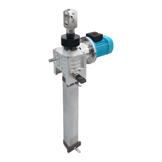
Released 1. Short description The ATLANTA TS-standard screw-jack gearboxes (series 61 3x xxx und 61 4x xxx) are used for the conver- sion of rotary motions into linear motions. They are mainly driven by three-phase motors. Manual operation is also possible. After consultation with ATLANTA other motors may be permissible as special version, e.g. -
Page 5: Proper Use
When operated in areas with explosion hazard the instructions identified by the symbol are to be observed. The ATLANTA screw-jack gearboxes may only be used for the conversion of rotary motions into linear motions in mechanical engineering applications under atmospheric pressure condi- tions. -
Page 6: Improper Use
When used in areas with explosion hazard, it may be necessary to measure the surface temper- ature and to ensure warning or cut-off, if the temperature of 65°C is exceeded. Differing working conditions require written approval by ATLANTA. 2.1. Improper use:... -
Page 7: Preparing The Installation
BWL 350 Operating and Maintenance Instructions 4100-001-12.93 Dept. TB/Gm Page TS - Screw Jack Gearbox Rev.Index B / 35865 Name Gansemer 2014-04-14 Translation from German original Date 13.07.2018 Released 3. Transport Transport and handling may be carried out only by qualified or specially trained personnel. - Page 8 Does the scope of delivery comply with the shipping documents? Report any shipping damage immediately to the forwarder. Report any visible damage/incompleteness immediately to ATLANTA An- triebssysteme E. Seidenspinner GmbH & Co. KG. Application in areas with explosion hazard: ...
- Page 9 BWL 350 Operating and Maintenance Instructions 4100-001-12.93 Dept. TB/Gm Page TS - Screw Jack Gearbox Rev.Index B / 35865 Name Gansemer 2014-04-14 Translation from German original Date 13.07.2018 Released 4.2. True-running check at the spindle of gear units with rotating spindle:...
-
Page 10: Installation
BWL 350 Operating and Maintenance Instructions 4100-001-12.93 Dept. TB/Gm Page TS - Screw Jack Gearbox Rev.Index B / 35865 Name Gansemer 2014-04-14 Translation from German original Date 13.07.2018 Released 5. Installation Mounting work may be carried out only by qualified or specially trained personnel. - Page 11 BWL 350 Operating and Maintenance Instructions 4100-001-12.93 Dept. TB/Gm Page TS - Screw Jack Gearbox Rev.Index B / 35865 Name Gansemer 2014-04-14 Translation from German original Date 13.07.2018 Released Installation dimension “x” [mm] Installation dimension “x” [mm] Gear unit with mechanical limit-switch set with inductive limit-switch set acc.
- Page 12 BWL 350 Operating and Maintenance Instructions 4100-001-12.93 Dept. TB/Gm Page TS - Screw Jack Gearbox Rev.Index B / 35865 Name Gansemer 2014-04-14 Translation from German original Date 13.07.2018 Released 5.2. Mounting the fork link / spherical plain bearing rod head / swivel head for gear units with non-rotating spindle: The fork link / spherical plain bearing head / swivel head is usually supplied non-assembled.
- Page 13 BWL 350 Operating and Maintenance Instructions 4100-001-12.93 Dept. TB/Gm Page TS - Screw Jack Gearbox Rev.Index B / 35865 Name Gansemer 2014-04-14 Translation from German original Date 13.07.2018 Released 5.3. Mounting the spindle nut for gear units with rotating spindle: Spindle and nut must be perfectly aligned.
- Page 14 BWL 350 Operating and Maintenance Instructions 4100-001-12.93 Dept. TB/Gm Page TS - Screw Jack Gearbox Rev.Index B / 35865 Name Gansemer 2014-04-14 Translation from German original Date 13.07.2018 Released Self-aligning running nuts can make up for a misalignment angle of max. 3° between axle of spindle and screwing surface of nut.
- Page 15 BWL 350 Operating and Maintenance Instructions 4100-001-12.93 Dept. TB/Gm Page TS - Screw Jack Gearbox Rev.Index B / 35865 Name Gansemer 2014-04-14 Translation from German original Date 13.07.2018 Released 5.5. Mounting the flange-nut swivel bearing in gear units with rotating spindles: The flange-nut swivel bearing is usually loosely enclosed with the gear unit supplied.
- Page 16 BWL 350 Operating and Maintenance Instructions 4100-001-12.93 Dept. TB/Gm Page TS - Screw Jack Gearbox Rev.Index B / 35865 Name Gansemer 2014-04-14 Translation from German original Date 13.07.2018 Released 5.7. Mounting the bellows: When used in areas with explosion hazard, it must be ensured that the bellows cannot come in touch with any attachments and will not brush against anything during operation, in order to avoid electrostatic charging.
- Page 17 BWL 350 Operating and Maintenance Instructions 4100-001-12.93 Dept. TB/Gm Page TS - Screw Jack Gearbox Rev.Index B / 35865 Name Gansemer 2014-04-14 Translation from German original Date 13.07.2018 Released 5.8. Mounting the pivot block or lugs: In the case of types TS2 and TS5 the pivot block is one piece. In the case of bigger gearbox- es there are lugs provided for the different swivelling directions.
- Page 18 BWL 350 Operating and Maintenance Instructions 4100-001-12.93 Dept. TB/Gm Page TS - Screw Jack Gearbox Rev.Index B / 35865 Name Gansemer 2014-04-14 Translation from German original Date 13.07.2018 Released 5.9. Mounting the swivel bolts: The interface between swivel pins and the adjacent construction must be rigid. Deflections cause additional stresses on the screws (both the swivel bolts and the pivot block / lugs) whereby they may be overloaded and may break.
- Page 19 Se- cure screws against loosening (e.g. with Loctite 243). Size TS 10 (Part number 61 84 500 and 61 84 510): To fix the motor flange to the gearbox, use the screw M8x20 DIN 7984 for the bore with the deeper counterbore.
- Page 20 Date 13.07.2018 Released Mounting sizes TS 25 to TS 100. In the case of these sizes, first screw the adapter ring to the gear unit and then the motor flange to the adapter ring. Screwing the adapter ring to the gear unit:...
- Page 21 13.07.2018 Released 5.11. Mounting the drive coupling: If the drive coupling is supplied by ATLANTA, it will usually be enclosed separately. Mount and fix the coupling as described in the enclosed operating and mounting instructions of the coupling manufacturer. When used in areas with explosion hazard, only couplings meeting the ATEX requirements may be used.
-
Page 22: Mounting The Motor
BWL 350 Operating and Maintenance Instructions 4100-001-12.93 Dept. TB/Gm Page TS - Screw Jack Gearbox Rev.Index B / 35865 Name Gansemer 2014-04-14 Translation from German original Date 13.07.2018 Released 5.12. Mounting the motor: Mount and attach the motor as described in the enclosed operating and mounting instructions of the motor manufacturer. -
Page 23: Mounting The Hand Wheel
BWL 350 Operating and Maintenance Instructions 4100-001-12.93 Dept. TB/Gm Page TS - Screw Jack Gearbox Rev.Index B / 35865 Name Gansemer 2014-04-14 Translation from German original Date 13.07.2018 Released 5.13. Mounting the hand wheel The hand wheel is usually supplied non-mounted. - Page 24 0.34 0.65 1.02 Example: Gearbox TS 25 with i=6 and trapezoidal-thread spindle Tr30x6 Nominal load of spindle in customer application: 13 kN 13 kN * 6 mm = ------------------------------------ + 0.36 Nm = 6.2 Nm 2 * π * 0.41 * 6* 0.87 The motor torque must not exceed 6.2 kN while moving the load.
- Page 25 BWL 350 Operating and Maintenance Instructions 4100-001-12.93 Dept. TB/Gm Page TS - Screw Jack Gearbox Rev.Index B / 35865 Name Gansemer 2014-04-14 Translation from German original Date 13.07.2018 Released 7. Mechanical start-up: The start-up may only be carried out by qualified or specially trained personnel.
- Page 26 Beacon EP 2 Shell: Gadus S2 V100 2 ATLANTA order code for 1 kg Klüber Microlube GB-0: 65 90 002 The electronically controlled lubricator should be taken in operation as described in the en- closed instructions BKI 102. For start-up fill the hose by means of a grease gun before mounting. Proper lubrication is ensured only when the connecting hose is completely filled with grease right into the nut.
- Page 27 BWL 350 Operating and Maintenance Instructions 4100-001-12.93 Dept. TB/Gm Page TS - Screw Jack Gearbox Rev.Index B / 35865 Name Gansemer 2014-04-14 Translation from German original Date 13.07.2018 Released 7.2. Test run of the screw-jack gearbox before installation: Before starting the test run, the gear unit must be secured against torsion and the torque...
- Page 28 BWL 350 Operating and Maintenance Instructions 4100-001-12.93 Dept. TB/Gm Page TS - Screw Jack Gearbox Rev.Index B / 35865 Name Gansemer 2014-04-14 Translation from German original Date 13.07.2018 Released Drawing 7.2.1 End positions for gear units with rotating spindle: Anschlusskonstruktion = adjacent construction Post the nameplate easily visible near the gear unit.
- Page 29 BWL 350 Operating and Maintenance Instructions 4100-001-12.93 Dept. TB/Gm Page TS - Screw Jack Gearbox Rev.Index B / 35865 Name Gansemer 2014-04-14 Translation from German original Date 13.07.2018 Released Drawing 7.2.2. End positions for gear units with non-rotating spindle: Max. Hub = …mm …mm...
- Page 30 This check has to be repeated after 10 hours work under operat- ing conditions. Additional attachments or alterations at the gear unit require written permission by ATLANTA. It must be ensured that no persons are endangered by the free rotating input-shaft end.
- Page 31 BWL 350 Operating and Maintenance Instructions 4100-001-12.93 Dept. TB/Gm Page TS - Screw Jack Gearbox Rev.Index B / 35865 Name Gansemer 2014-04-14 Translation from German original Date 13.07.2018 Released Gear unit Screw size Depth of thread Strength class of Tightening...
- Page 32 BWL 350 Operating and Maintenance Instructions 4100-001-12.93 Dept. TB/Gm Page TS - Screw Jack Gearbox Rev.Index B / 35865 Name Gansemer 2014-04-14 Translation from German original Date 13.07.2018 Released 7.4. Installation of screw-jack gearbox with non-rotating spindle in the system:...
- Page 33 BWL 350 Operating and Maintenance Instructions 4100-001-12.93 Dept. TB/Gm Page TS - Screw Jack Gearbox Rev.Index B / 35865 Name Gansemer 2014-04-14 Translation from German original Date 13.07.2018 Released Warning! Rotating or straight moving parts may catch pieces of clothing, hair and members of the body and injure persons.
- Page 34 BWL 350 Operating and Maintenance Instructions 4100-001-12.93 Dept. TB/Gm Page TS - Screw Jack Gearbox Rev.Index B / 35865 Name Gansemer 2014-04-14 Translation from German original Date 13.07.2018 Released When all connection parameters are met, perform several lifting strokes without load.
- Page 35 BWL 350 Operating and Maintenance Instructions 4100-001-12.93 Dept. TB/Gm Page TS - Screw Jack Gearbox Rev.Index B / 35865 Name Gansemer 2014-04-14 Translation from German original Date 13.07.2018 Released 7.5. Installation of the screw-jack gearbox with rotating spindle in the system:...
- Page 36 BWL 350 Operating and Maintenance Instructions 4100-001-12.93 Dept. TB/Gm Page TS - Screw Jack Gearbox Rev.Index B / 35865 Name Gansemer 2014-04-14 Translation from German original Date 13.07.2018 Released Warning! Rotating or straight moving parts may catch pieces of clothing, hair and members of the body and injure persons.
- Page 37 BWL 350 Operating and Maintenance Instructions 4100-001-12.93 Dept. TB/Gm Page TS - Screw Jack Gearbox Rev.Index B / 35865 Name Gansemer 2014-04-14 Translation from German original Date 13.07.2018 Released Mounting the bellows (see paragraph 5.7): Mount the spindle nut observing para. 5.3. Mount the nut on the attachment without tension.
- Page 38 BWL 350 Operating and Maintenance Instructions 4100-001-12.93 Dept. TB/Gm Page TS - Screw Jack Gearbox Rev.Index B / 35865 Name Gansemer 2014-04-14 Translation from German original Date 13.07.2018 Released 7.6. Screw-jack lifting systems comprising several gearboxes: When systems consist of several screw-jack gearboxes, the components where the adjacent attachment is to be fastened must be carefully adjusted in height so that the gearboxes will be uniformly loaded and no tensions occur.
- Page 39 BWL 350 Operating and Maintenance Instructions 4100-001-12.93 Dept. TB/Gm Page TS - Screw Jack Gearbox Rev.Index B / 35865 Name Gansemer 2014-04-14 Translation from German original Date 13.07.2018 Released Length (mm) Permissible angular displacement: The angular displacement must be checked at each flange. The deviation S must not exceed the following value: S <...
- Page 40 BWL 350 Operating and Maintenance Instructions 4100-001-12.93 Dept. TB/Gm Page TS - Screw Jack Gearbox Rev.Index B / 35865 Name Gansemer 2014-04-14 Translation from German original Date 13.07.2018 Released 7.6.1 Mounting the universal shaft with key connection (60 83 x0x): This universal shaft has a bore with keyway on both flanges.
- Page 41 BWL 350 Operating and Maintenance Instructions 4100-001-12.93 Dept. TB/Gm Page TS - Screw Jack Gearbox Rev.Index B / 35865 Name Gansemer 2014-04-14 Translation from German original Date 13.07.2018 Released the aluminum bushings thus increasing the frictional application pressure between these parts.
- Page 42 BWL 350 Operating and Maintenance Instructions 4100-001-12.93 Dept. TB/Gm Page TS - Screw Jack Gearbox Rev.Index B / 35865 Name Gansemer 2014-04-14 Translation from German original Date 13.07.2018 Released 7.6.2 Mounting the universal shaft with clamped connection (60 83 x1x): One flange of this universal shaft has a bore with keyway and the other one a smooth bore with clamping hub and screw.
- Page 43 BWL 350 Operating and Maintenance Instructions 4100-001-12.93 Dept. TB/Gm Page TS - Screw Jack Gearbox Rev.Index B / 35865 Name Gansemer 2014-04-14 Translation from German original Date 13.07.2018 Released Anaerobic adhesives (such as Loctite, Omnifit etc.) undo the adhesion of the rubber on the metal thus leading to the destruction of the coupling.
- Page 44 BWL 350 Operating and Maintenance Instructions 4100-001-12.93 Dept. TB/Gm Page TS - Screw Jack Gearbox Rev.Index B / 35865 Name Gansemer 2014-04-14 Translation from German original Date 13.07.2018 Released 7.6.3 Mounting the pillow blocks: Use only pillow blocks with bearings on clamping sleeves. Only this type of fastening will avoid the eccentric fixing of the universal shaft.
-
Page 45: Operation
BWL 350 Operating and Maintenance Instructions 4100-001-12.93 Dept. TB/Gm Page TS - Screw Jack Gearbox Rev.Index B / 35865 Name Gansemer 2014-04-14 Translation from German original Date 13.07.2018 Released 8. Operation Forces, cycle times, torque or any other relevant working conditions on which the lay- out is based, must not be exceeded during the practical operation –... -
Page 46: Maintenance Intervals
BWL 350 Operating and Maintenance Instructions 4100-001-12.93 Dept. TB/Gm Page TS - Screw Jack Gearbox Rev.Index B / 35865 Name Gansemer 2014-04-14 Translation from German original Date 13.07.2018 Released 9. Maintenance Maintenance work may only be carried out by qualified or specially trained personnel! Monitoring and protective equipment must not be put out of operation. - Page 47 Do not clean the gear unit, and in particular the area of the seals, with sharp-edged objects. Cleaning with solvents or cleaning agents is only permissible if these are released in writing by ATLANTA E.Seidenspinner GmbH & Co. KG. After cleaning the basic gear unit it is necessary to grease the spindle and the nut again.
- Page 48 If operated under different working conditions, we recommend to remove the old grease and clean the gear unit after approx. 600 operating hours or 2 years and to fill it with new grease. ATLANTA recommendation: Blasolube 306 from Fa. Blaser The gear unit is supplied filled with this type of grease.
- Page 49 BWL 350 Operating and Maintenance Instructions 4100-001-12.93 Dept. TB/Gm Page TS - Screw Jack Gearbox Rev.Index B / 35865 Name Gansemer 2014-04-14 Translation from German original Date 13.07.2018 Released Then remove the fork link, spherical plain bearing rod head, swivel head, or the fixing flange from the attachment and rotate the spindle downwards by 2-3 rotations.
- Page 50 Gear unit with non-rotating spindle: The trapezoidal-thread nut is integrated in the worm wheel and is within the gear unit. There- fore the gear unit must be sent to ATLANTA for replacing the trapezoidal-thread nut and, if necessary, the spindle.
- Page 51 BWL 350 Operating and Maintenance Instructions 4100-001-12.93 Dept. TB/Gm Page TS - Screw Jack Gearbox Rev.Index B / 35865 Name Gansemer 2014-04-14 Translation from German original Date 13.07.2018 Released Replacing the spindle: 9.7. The spindle is a safety-relevant component. It transmits the axial forces and the torque between spindle and gearbox.
- Page 52 BWL 350 Operating and Maintenance Instructions 4100-001-12.93 Dept. TB/Gm Page TS - Screw Jack Gearbox Rev.Index B / 35865 Name Gansemer 2014-04-14 Translation from German original Date 13.07.2018 Released 10. Storing If the gear unit is not installed immediately after delivery, the following precautions have to be taken: ...
- Page 53 BWL 350 Operating and Maintenance Instructions 4100-001-12.93 Dept. TB/Gm Page TS - Screw Jack Gearbox Rev.Index B / 35865 Name Gansemer 2014-04-14 Translation from German original Date 13.07.2018 Released 12.1. Motor connection diagram for three-phase motor without brake and limit switch at the protective tube for gear units with non-rotating spindle: BWL_350_B.DOC...
- Page 54 BWL 350 Operating and Maintenance Instructions 4100-001-12.93 Dept. TB/Gm Page TS - Screw Jack Gearbox Rev.Index B / 35865 Name Gansemer 2014-04-14 Translation from German original Date 13.07.2018 Released Endschalter für stehende Spindel Limit switches for non-rotating spin- am Schutzrohr:...
- Page 55 BWL 350 Operating and Maintenance Instructions 4100-001-12.93 Dept. TB/Gm Page TS - Screw Jack Gearbox Rev.Index B / 35865 Name Gansemer 2014-04-14 Translation from German original Date 13.07.2018 Released 12.2. Motor connection diagram for three-phase motor with brake for gear units with rotating spindle: BWL_350_B.DOC...
Need help?
Do you have a question about the TS and is the answer not in the manual?
Questions and answers