Table of Contents
Advertisement
Quick Links
215-1845 Rev. B; ECN 17-05-068
© 2017 Bradley
Page 1 of 12
11/21/2017
Installation
S19-322
Recessed Emergency Signaling System
Table of Contents
Pre-Installation Information . . . . . . . . . . . . . . . . . . . . . . . . . . 2-3
Components . . . . . . . . . . . . . . . . . . . . . . . . . . . . . . . . . . . . . . . 4
Install Flow Switch . . . . . . . . . . . . . . . . . . . . . . . . . . . . . . . . . . 5
Mount Signaling Assembly . . . . . . . . . . . . . . . . . . . . . . . . . . . 6
Connect Signaling Assembly . . . . . . . . . . . . . . . . . . . . . . . . . . 6
Complete Electrical Supply Connections . . . . . . . . . . . . . . . . . 7
Test the Signaling System . . . . . . . . . . . . . . . . . . . . . . . . . . . . 7
Maintenance . . . . . . . . . . . . . . . . . . . . . . . . . . . . . . . . . . . . . . 8
Remove Sensing Option . . . . . . . . . . . . . . . . . . . . . . . . . . . . . 8
Service of Lights . . . . . . . . . . . . . . . . . . . . . . . . . . . . . . . . . . . 8
Troubleshooting . . . . . . . . . . . . . . . . . . . . . . . . . . . . . . . . . . . . 9
Service Parts . . . . . . . . . . . . . . . . . . . . . . . . . . . . . . . . . . . . . 10
Wiring Diagram . . . . . . . . . . . . . . . . . . . . . . . . . . . . . . . . . . . 11
Schematic . . . . . . . . . . . . . . . . . . . . . . . . . . . . . . . . . . . . . . . 12
Menomonee Falls, WI 53052 USA
800 BRADLEY (800 272 3539)
P.O. Box 309
+1 262 251 6000
bradleycorp.com
Advertisement
Table of Contents

Related Manuals for Bradley S19-322


Summary of Contents for Bradley S19-322
-
Page 1: Table Of Contents
Schematic . . . . . . . . . . . . . . . . . . . . . . . . . . . . . . . . . . . . . . . 12 P.O. Box 309 Menomonee Falls, WI 53052 USA 215-1845 Rev. B; ECN 17-05-068 800 BRADLEY (800 272 3539) © 2017 Bradley +1 262 251 6000 Page 1 of 12 11/21/2017 bradleycorp.com... -
Page 2: Pre-Installation Information
Failure to do so may result in major product and/or property damage. Constant power supply to safety equipment is necessary for it to function. Avoid cleaners containing organic solvents, alcohols and hydrocarbons. Rinse with potable water after cleaning. Bradley • 215-1845 Rev. B; ECN 17-05-068 11/21/2017... - Page 3 The ANSI/ISEA Z358.1 standard requires an uninterrupted supply of flushing fluid. Bradley plumbed emergency fixtures require a minimum of 30 PSI (0.21MPa) flowing pressure.
-
Page 4: Components
System is prewired. Installer connects ONLY ground black and white wires. Brass Adapter and Tee 2-3/8" (60mm) for 1/2" (eyewash) eyewash or or 1¼" (drench 3-9/16" (91mm) for shower) NPT Inlet drench shower and Outlet Bradley • 215-1845 Rev. B; ECN 17-05-068 11/21/2017... -
Page 5: Install Flow Switch
. minimum 6 inches from any fittings) For eye or eye/face wash units To 1/2" Water Supply Piping supplied by Flow Switch installer (must be minimum 3 inches from any fittings) Bradley • 215-1845 Rev. B; ECN 17-05-068 11/21/2017... -
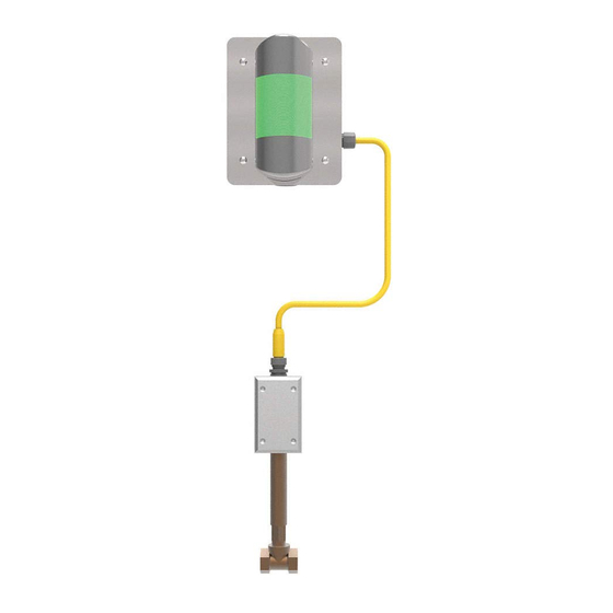
Page 6: Mount Signaling Assembly
Make sure cable is not taut to prevent undue stress to cable and connector. Tighten the locking collar on the female cable socket by rotating it clockwise after plugging in . This makes a good watertight connection . Bradley • 215-1845 Rev. B; ECN 17-05-068 11/21/2017... -
Page 7: Complete Electrical Supply Connections
The signaling system will beacon/signal light will continue to flash continue to operate so long as either the eyewash as long as the fixture is activated. or drench shower is still in use. Bradley • 215-1845 Rev. B; ECN 17-05-068 11/21/2017... -
Page 8: Maintenance
Installation Signaling System Maintenance The Bradley Emergency Signaling System is designed to be virtually maintenance free . An occasional damp cloth wiping of the clear dust cover is all that is needed to ensure maximum visual attention-getting ability . The horn is factory-set at the loudest possible sound level, 85 decibels at 3 feet . -
Page 9: Troubleshooting
Check that there is 24VDC being supplied from the power supply mounted on the print circuit board in the signal station enclosure . Component failure . Check light connections and filament in the light . Bradley • 215-1845 Rev. B; ECN 17-05-068 11/21/2017... -
Page 10: Service Parts
Flow Switch - 1-1/4" T-DPDT 161-026 Nut, 1/4-20 Hex 269-1522 Flow Switch - 1/2" T DPDT 269-2460 Plug, 3/4" Conduit Light/horn (item 1) includes hardware for attaching it to panel (item 3). Bradley • 215-1845 Rev. B; ECN 17-05-068 11/21/2017... -
Page 11: Wiring Diagram
S19-322 Installation Wiring Diagram Bradley • 215-1845 Rev. B; ECN 17-05-068 11/21/2017... -
Page 12: Schematic
INTERNAL JUMPER TERMINAL BLOCK HORN CONNECTION COMPONENT SOLDERED FLOW SWITCH CONNECTION NORMALLY OPEN FLOW SENSOR FUSE NORMALLY OPEN NORMALLY OPEN CONTACT SWITCH NORMALLY CLOSED NORMALLY CLOSED CONTACT SWITCH RELAY COIL LAMP/HORN MODULE Bradley • 215-1845 Rev. B; ECN 17-05-068 11/21/2017...
Need help?
Do you have a question about the S19-322 and is the answer not in the manual?
Questions and answers