
Related Manuals for Cetetherm Micro


Summary of Contents for Cetetherm Micro
- Page 1 Installation, service and operating instruction Cetetherm Micro Heating & domestic hot water substation for apartments and single family houses DOC1355, 16-03-2021...
- Page 2 This manual is published by Cetetherm. Cetetherm can without further notice make changes and improvements to the content in this manual if it is necessary due to printing mistakes, wrong information or changes in the hardware or software. All these types of changes will be included in future release of the manual.
-
Page 3: Table Of Contents
General warnings ............................7 Micro STC and Micro STC2 warnings ....................... 7 Operating instructions ......................8 General operation ............................8 Heating operation Micro STC and Micro STC2 ..................8 Heating operation Micro RTC ........................8 Safety equipment/inspection ........................8 Product overview ........................9 Product overview AquaMicro ........................ - Page 4 Grundfos Alpha2L settings ........................43 Pump curve ............................. 44 Electrical circuit diagram ..................... 45 Micro RTC ............................... 45 Micro STC and Micro STC2 ........................46 Service instructions ......................47 General service instructions ........................47 Tap water temperature too low ......................47 Tap water temperature too high ......................
- Page 5 Change the flow switch ........................... 57 Operating data and performance ..................58 Operating data ............................58 AquaMicro ............................58 Micro DPC, Micro RTC, Micro HTC, Micro STC, Micro STC2 ............58 Technical Data ............................59 Measure sketch ............................60 Options ..........................61 Safety thermostat ............................
-
Page 6: General Information
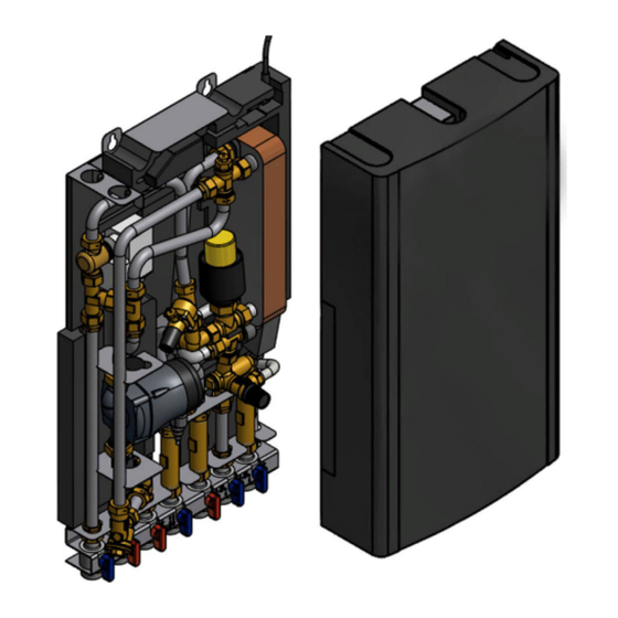
A pre-programmed control unit and a power cable already fitted with a plug make things even simpler to allow immediate start-up. Micro is designed for hanging on wall and is mounted on an insulated frame and includes an insulated cover. Better insulation means less energy usage and better energy efficiency. -
Page 7: General Warnings
Start heating circulation by first opening the valves in the primary heating supply and then return lines, to avoid pollutions in the system. Open the valves slowly to avoid pressure surges. Micro STC and Micro STC2 warnings Before the substation is connected to the electrical supply, make sure that the heating system is topped up with water. -
Page 8: Operating Instructions
Heating operation Micro STC and Micro STC2 With a Micro STC or a Micro STC 2, the heating circuit is controlled in relation to outdoor temperature (option) and/or desired room temperature by means of a room thermostat and temperature sensor. When no heat is needed, the circulation pump in the heating circuit stops automatically, but is started regularly to make sure that it does not seize up during long idle periods. -
Page 9: Product Overview
Cetetherm Micro Installation, service and operating instruction 3 Product overview Note: The product overview pictures are shown without the insulation. Product overview AquaMicro Picture 1 Heat exchanger and temperature Adapter for Hot water flow meter controller for hot water Control valve for hot water... -
Page 10: Product Overview Micro Dpc
Cetetherm Micro Installation, service and operating instruction Product overview Micro DPC Picture 2 1 Heat exchanger and temperature 10 Heating network media, supply controller for hot water 2 Control valve for hot water 11 Heating network media, return 3 Temperature sensor connection,... -
Page 11: Product Overview Micro Rtc
Cetetherm Micro Installation, service and operating instruction Product overview Micro RTC Picture 3 1 Heat exchanger and temperature Cold water outlet (cw) controller for hot water 2 Control valve for hot water Hot water (hw) 3 Temperature sensor connection, Differential pressure controller... -
Page 12: Product Overview Micro Stc
Cetetherm Micro Installation, service and operating instruction Product overview Micro STC Picture 4 Differential pressure controller *) Heat exchanger and temperature controller for hot water Control valve for hot water Heating circuit, return Temperature sensor connection, Heating circuit, supply heating media supply... -
Page 13: Product Overview Micro Stc2
Cetetherm Micro Installation, service and operating instruction Product overview Micro STC2 Picture 5 Heat exchanger and temperature Differential pressure controller *) controller for hot water Control valve for hot water Heating circuit, return Temperature sensor connection, Heating circuit, supply heating media supply... -
Page 14: Product Overview Micro Htc
Cetetherm Micro Installation, service and operating instruction Product overview Micro HTC Picture 6 1 Heat exchanger and temperature 11 Heating network media, return controller for hot water 2 Control valve for hot water 12 Cold water (cw) 3 Temperature sensor connection,... -
Page 15: Installation
AquaMicro: at least 50kPa and at most 600 kPa Micro DPC, RTC STC, STC2 and HTC at least 50 kPa and at most 400 kPa Where the differential pressure is higher, a differential pressure controller should be added to the installation. -
Page 16: Mounting Options General
Set point °C (approx.) Cetetherm recommends that the tap water temperature is set to 15º less than the primary inlet temperature with a Micro HTC NOTE: Make sure that no cold water is mixed with the hot water while making this adjustment. -
Page 17: Commissioning Advice Micro Stc And Micro Stc2
Cetetherm Micro Installation, service and operating instruction Commissioning advice Micro STC and Micro STC2 Set the control mode on the control panel. • Control panel Round has been pre-set at the factory to use control mode; Outside Temperature Control (OTC control). To change control mode see 6 Room thermostat Round. -
Page 18: Installing The Room Thermostat Round
Cetetherm Micro Installation, service and operating instruction Installing the room thermostat Round 1 Removing power supply 2 Placement 3 Removing the dial 4 Removing the thermostat 5a Mounting direct on the wall 5b Mounting in wall socket 7 Mounting the thermostat... -
Page 19: Installing The Control Panel Cm737
Cetetherm Micro Installation, service and operating instruction Installing the control panel CM737 The control panel CM737 can be used as a room thermostat. Before installation make sure that the electrical power supply is disconnected. Install the room thermostat at an appropriate location that is representative to the indoor temperature. - Page 20 Cetetherm Micro Installation, service and operating instruction Picture 12...
-
Page 21: Installing The Outdoor Temperature Sensor
Cetetherm Micro Installation, service and operating instruction Installing the outdoor temperature sensor Connect the outdoor temperature sensor to the electric box. With a conductor area of 0.6 mm the maximum cable length is 50 metres, maximum 5Ω/conductor. If the outdoor temperature sensor is connected later, for example in a construction period, the room thermostat must be restarted and configurated. -
Page 22: Cm737- Settings To Be Done After Start-Up
Cetetherm Micro Installation, service and operating instruction 5 CM737- settings to be done after start-up 1. Press the MAN (8) button for a fixed set point (no reduction) of the room temperature. 2. Adjust the room temperature with the increase/decrease buttons on the right (6). -
Page 23: Room Thermostat Round
Cetetherm Micro Installation, service and operating instruction 6 Room thermostat Round General The room thermostat Round controls the supply temperature to the heating system. First time the room thermostat is started is use default control mode Outside Temperature Control (OTC control). -
Page 24: Control Modes
Cetetherm Micro Installation, service and operating instruction Control modes The room thermostat has five different control modes to select between; the default mode is Outside Temperature Control (OTC control). 1. Room temperature control RTC Supply setpoint is calculated based on the room temperature setpoint and the actual room temperature. -
Page 25: Otc Control Mode, Default Setting
Cetetherm Micro Installation, service and operating instruction OTC control mode, default setting The room thermostat controls the indoor Heat curve 10 has been set at the factory. temperature as a function of the measured outside air temperature. The heat curve is the ratio between the measured outside air temperature and the calculated supply water temperature. -
Page 26: Display Symbols
Cetetherm Micro Installation, service and operating instruction Display symbols Control Display will show mode Shows the actual room temperature with one decimal and in 0.5 steps when the room temperature is used. Shows the room temperature setpoint with one decimal and in 0.5 steps when temperature control mode is OTC. -
Page 27: Fault Messages On The Room Thermostat
Cetetherm Micro Installation, service and operating instruction Fault messages on the room thermostat If a spanner is visible on the display there is an ongoing alarm. On the display Cause Fault code is shown on 7-segments Internal fault (like sensor fault) -
Page 28: Factory Settings, Room Thermostat
Cetetherm Micro Installation, service and operating instruction Factory settings, room thermostat Setting/function Default Value Setting/function Default Value Control mode Min Room setpoint 10.0 °C Room Temp Setpoint 17.0 °C Max Room setpoint 27.0 °C Constant Supply Temp Setpoint 40 °C Min Supply setpoint 0 °C... -
Page 29: Connect The Round To Internet Via Gateway
Cetetherm Micro Installation, service and operating instruction 7 Connect the Round to internet via Gateway 1. Connect the Gateway to power LED status on Gateway 2. Connect the Gateway to internet router 3. Bind the Gateway to room thermostat Round... -
Page 30: Troubleshooting
Cetetherm Micro Installation, service and operating instruction LED on Gateway should turn solid green when successfully registered. Download the free app Total Connect Comfort Europé. Choose ”Create account”. Fill in all fields. A conformation mail is send to the mail address. -
Page 31: Clearing Binding Between Round And The Gateway
Cetetherm Micro Installation, service and operating instruction Clearing binding between Round and the Gateway If Round needs to be replaced the binding must be cleared from the Gateway first. As the heating schedule is stored by the Gateway (and not by the App) it will be cleared and need to be set up again. -
Page 32: Installing The Room Thermostat Cm737
Time change buttons 5 Temperature display Holiday function button Micro STC and Micro STC2 with CM737 are supplied fully wired. The wiring conforms to the applicable rules for CE marking and has undergone electrical safety tests testing and function tests. OK-button (9) When changing settings/values in CM737 the numbers in the display is flashing. -
Page 33: Choosing The Operating Mode
To set the operating mode press either of the AUTO, MAN or OFF buttons. The screen indicates which mode is currently active. NOTE: Cetetherm recommends the mode MAN. MAN (fixed) the room thermostat acts with a fixed set point throughout the day. -
Page 34: Holiday Function
Cetetherm Micro Installation, service and operating instruction Holiday function The holiday function allows you to set a constant temperature (default = 10 °C) for a specified number of days (from 1 - 99 days). This saves energy and related costs when the house is empty but resumes normal operation on the day of return. -
Page 35: Operating Mode Auto
Cetetherm Micro Installation, service and operating instruction Operating mode Auto The Built-in Heating Program The built-in heating program has four temperature level changes per day that can be set between 3.00am and 2.50am the following day - allowing the evening temperature to maintain after midnight. Each temperature level can be set between 5 °C and 35 °C, and adjusted in 0.5 °C increments. -
Page 36: Modifying The Heating Program
Cetetherm Micro Installation, service and operating instruction Modifying the heating program To change the heating program: a) Press either of the PROGRAM buttons to enter the programming mode. The time /temperature settings for period on Monday day 1 will be flashing. The active period is highlighted by a flashing square around the numbers at the bottom of the screen and the selected day is shown with the day indicator. -
Page 37: Activation Of Installer Parameters Cm737
Cetetherm Micro Installation, service and operating instruction 9 Activation of installer parameters CM737 Installer Mode is used to alter the system settings for specific applications, to use the special features of the room thermostat in a different way or to alter the factory present parameters. Parameters are divided into... -
Page 38: Cm737-Category 1: Control Panel Settings
Cetetherm Micro Installation, service and operating instruction CM737–Category 1: Control panel settings Parameter Para- Factory Optional Setting meter Default Display Description Setting AM-PM / 24hr Display 1:CL 24/12 24hr. or AM/PM clock display format Reset Time/ Temp 2:rP 0: time or temp has been changed... -
Page 39: Cm737-Category 3: Setting And Displaying Sensor Values
Cetetherm Micro Installation, service and operating instruction CM737-Category 3: Setting and displaying sensor values Parameter Para- Factory Optional Setting meter Default Display Description Setting Maximum supply 1:CH 30 to 80 Maximum supply temp set point for heating. temperature set point... -
Page 40: Troubleshooting The Cm737
Cetetherm Micro Installation, service and operating instruction 10 Troubleshooting the CM737 Symptom Possible Cause Remedy The CM737 receives power The CM737 is not connected to A flashing symbol supply from the heating the correct terminals of the appears on the display within appliance, but no information. -
Page 41: Fault Codes On The Cm737
Cetetherm Micro Installation, service and operating instruction Fault Codes on the CM737 If a spanner is visible on the display, there is an on ongoing alarm. Press the Info-button to view the fault code. Error source Error code No fault (power-up) -
Page 42: Differential Pressure Control Valve, Dpc
Cetetherm Micro Installation, service and operating instruction 11 Differential pressure control valve, DPC Adjusting the DPC must be carried out by an authorized service technician. Setting the DPC valve Set the valve to the differential pressure 25kPa. Start with the valve at minimum position and then open with 3 numbers of turns. -
Page 43: Pump Settings And Pump Performance
Cetetherm Micro Installation, service and operating instruction 12 Pump settings and pump performance The Micro STC is equipped with a Grundfos Alpha2L pump. Grundfos Alpha2L settings Picture 23 Settings Pump curve Function Lowest proportional The duty point of the pump will move up or down on the lowest pressure curve proportional-pressure curve, depending on the heating demand. -
Page 44: Pump Curve
Cetetherm Micro Installation, service and operating instruction Pump curve Picture 24... -
Page 45: Electrical Circuit Diagram
Cetetherm Micro Installation, service and operating instruction 13 Electrical circuit diagram Micro RTC Picture 25... -
Page 46: Micro Stc And Micro Stc2
Cetetherm Micro Installation, service and operating instruction Micro STC and Micro STC2 Picture 26... -
Page 47: Service Instructions
The temperature should be minimum 50 °C. Cetetherm recommends that the primary inlet temperature is at least 10º higher than the tap water temperature. NOTE: Make sure that no cold water is mixed with the hot water while making this adjustment. -
Page 48: Hot Water Temperature Unstable Or Too Low
Cetetherm Micro Installation, service and operating instruction Hot water valve and/or Check the valve according to 15.1 Check the function of the valve for hot water actuator does not work If the water temperature is too high when the handle is in position 0, the actuator or the exchanger is damaged and requires replacing. -
Page 49: Stc Service Instructions
Cetetherm Micro Installation, service and operating instruction STC service instructions Hand manoeuvre of the heating actuator The room thermostat must be without current when manoeuvring the actuator by hand. NOTE: if manually adjusting the actuator, the operator control panel must be restarted before use. -
Page 50: Disturbing Noise From The Circulation Pump/ Noise In The Radiator System
Cetetherm Micro Installation, service and operating instruction Heating supply Check that the heating supply temperature sensor and outdoor temperature temperature sensor and sensor are correctly sited and working. outdoor temperature sensor (option) does not Control panel Round: work Supply temperature can only be viewed in control mode 4 and 5. -
Page 51: Service Actions For The Installer
Cetetherm Micro Installation, service and operating instruction 15 Service actions for the installer Check the function of the valve for hot water Service actions must be carried out by an authorized service technician. Close the shutoff valves for the Heating network supply and Heating network return together with the cold and hot water. -
Page 52: Check The Function Of The Heating Actuator And Valve
Cetetherm Micro Installation, service and operating instruction Check the function of the heating actuator and valve Service actions must be carried out by an authorized service technician. The room thermostat must be without current when manoeuvring the actuator by hand. -
Page 53: Maintenance And Repairs
Cetetherm Micro Installation, service and operating instruction 16 Maintenance and repairs When carrying out repairs, please contact your local service partner. Before starting out repairs always close the correct shutoff valves. When dismounting a component there will be water coming out, hot and under pressure. -
Page 54: Change The Hot Water Actuator And Heat Exchanger
Cetetherm Micro Installation, service and operating instruction Change the hot water actuator and heat exchanger The temperature and the pressure of the district heating water are very high. Only qualified technicians can work with the district heating substation. Incorrect operation may cause serious personal injury and result in damage to the building. -
Page 55: Change The Heating Actuator
Cetetherm Micro Installation, service and operating instruction Change the heating actuator Maintenance and repairs must be carried out by an authorized service technician. 1. Disconnect the electrical power supply. 2. Disconnect the cable from heating actuator in the connection box. -
Page 56: Change Pump Components Or The Complete Pump
Cetetherm Micro Installation, service and operating instruction Change pump components or the complete pump Maintenance and repairs must be carried out by an authorized service technician. Before starting out repairs, close the shutoff valves heating network supply, heating network return, heating supply and heating return. . -
Page 57: Change The Differential Pressure Control Valve
Cetetherm Micro Installation, service and operating instruction Change the differential pressure control valve The temperature and the pressure of the district heating water are very high. Only qualified technicians can work with the district heating substation. Incorrect operation may cause serious personal injury and result in damage to the building. -
Page 58: Operating Data And Performance
(l/s) Hot water circuit 80-25/10-55 0,34 0,42 70-25/10-58 0,19 0,18 65-25/10-50 0,33 0,33 Micro DPC, Micro RTC, Micro HTC, Micro STC, Micro STC2 Performance at available differential pressure 50-400 kPa Designed Capacity Primary Actual Secondary temperature (kW) flow return temp. -
Page 59: Technical Data
400x120x630 (mm, WxDxH) • Without cover Weight 12-15kg, cover 2kg Electrical connection 230 V, 1-phase, 50 W Micro STC & Micro STC2 • 230 V, 1-phase, 25 W Micro RTC • 230 V, single phase, 2 W Micro HTC •... -
Page 60: Measure Sketch
Cetetherm Micro Installation, service and operating instruction Measure sketch Picture 40... -
Page 61: Options
Cetetherm Micro Installation, service and operating instruction 18 Options The mounting instructions are described for a new installation. If the kits are supposed to be installed on an already installed subsystem, release the water pressure and disconnect the electrical power supply before starting. -
Page 62: First Fix-Jig
Installation, service and operating instruction First fix-jig To save time and efficiency the installation, Cetetherm offers a first-fix- jig including shut-off valves. The first fix- jig is available in three different models, with five, six or seven shut-off valves. Picture 43... - Page 64 Cetetherm AB Fridhemsvägen 15 372 38 Ronneby – Sweden www.cetetherm.com...
Need help?
Do you have a question about the Micro and is the answer not in the manual?
Questions and answers