
Summary of Contents for Spraying Systems TeeJet 844-AB
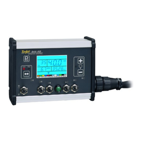
- Page 1 844-AB sprAyer control u s e r g u i d e m A n u A l For use with software version 4.02.
- Page 2 Copyrights © 2013 TeeJet Technologies. All rights reserved. No part of this document or the computer programs described in it may be reproduced, copied, photocopied, translated or reduced in any form or by any means, electronic or machine readable, recording or otherwise, without prior written consent from TeeJet Technologies.
-
Page 3: Table Of Contents
844-AB Table of Contents cHApter 1 – introduction Power On The Console ......................................1 Power Off The Console......................................1 cHApter 2 – ApplicAtion mode Airblast Mode ......................................... 2 Vineyard Mode ........................................2 cHApter 3 – oem setup Application Type ........................................2 Number of Sections ...................................... - Page 4 844-AB Minimum Pressure Setting ....................................11 Density (Liquid Specific Gravity) ...................................11 Communications ........................................12 Faces per Section Setting (HC Mode only) ..............................12 cHApter 5 – swAtH widtH presets Selecting Swath Preset .....................................13 cHApter 6 – ApplicAtion setup Preset Flow Rate Selection ....................................14 Nozzles per Face .........................................14 Target Application Rate ....................................14 Calculation Diagnostic .....................................15...
-
Page 5: Chapter 1 - Introduction
844-AB cHApter 1 – introduction This User Guide provides information for software version 4.02. Make sure that all hardware components are properly installed and tested. Before starting the programming process, confirm that the console and all sensors are working properly. IMPORTANT! Before beginning, review the following program Guidelines that control the programming process. -
Page 6: Chapter 2 - Application Mode
844-AB cHApter 2 – ApplicAtion mode cHApter 3 – oem setup The 844-AB gives the possibility of working in two different ways OEM Setup mode contains the options that customize the controller to fit the application. Therefore, the console should be set up and to the sprayer or sprayer components. -
Page 7: Minimum Voltage
844-AB minimum Voltage display stable This will determine the minimum voltage that can be applied to the This will determine allowed tolerance percentage on the displayed dose regulation valve. If too low, the valve won’t fine tune the dose rate. If rate. -
Page 8: Memory Option
844-AB cHApter 4 – system setup memory option This feature enables the user counters. System Setup mode contains the options that customize the controller to the sprayer or sprayer components. These include calibration steps Select NO to disable this feature or YES to enable it. and parameters that will rarely change once programmed. -
Page 9: Units Of Measurement
844-AB units of measurement sensor selection The 844-AB is capable of working in either US or SI (Standard The 844-AB can accommodate a flow meter, pressure transducer or International metric). Use the Plus and Minus keys to switch both. Sensor Selection instructs the console which sensor is being units. -
Page 10: Flow Meter Pulses
844-AB Engage the sprayer pump. Turn the boom sections “On” and begin Flow meter pulses spraying a known volume of fluid (e.g. 100 gallons/400 liters). As the During the Flow Meter Pulses step, the symbol (flow meter turbine) known amount is sprayed, the console will count the pulses. After the will flash at the top of the console. -
Page 11: Pressure Transducer Low Pressure Calibration (P Ref)
844-AB pressure transducer low pressure pressure transducer maximum rating (p Hi) calibration (p ref) The Pressure Transducer Maximum Rating establishes the maximum rating of the pressure transducer. This number can be found stamped The Pressure Transducer Low Pressure Calibration step is used to on the pressure transducer. -
Page 12: Manual Calculation
844-AB Figure 29: Speed Sensor Automatic Calibration the Program key to save the value and advance to the next program step. Radar Speed Pulses Figure 31: Radar Speed Sensor Drive toward the initial point of the of designated 300 feet / 100 meters. -
Page 13: Simulated Ground Speed
844-AB simulated ground speed reference Flow rate per section Simulated ground speed allows the console and sprayer to be tested AB Mode – The flow rate for each section of the sprayer must be input (and actually spray water) without physically moving the sprayer. This into the 844-AB console so that the necessary adjustments can be can and should be tested prior to any spraying activity. -
Page 14: Reference Pressure
844-AB regulating Valve response time 2. Reference Pressure Operating conditions may require a higher or lower response speed Before entering the reference flow, determine the pressure at which the for the regulating valve. To change the response time number, use the flow will be referenced. -
Page 15: Pressure Regulating Mode
844-AB pressure regulating mode minimum pressure setting Pressure Regulating mode directs the 844-AB to the location of the The Minimum Pressure Setting establishes the minimum pressure the regulating valve plumbing. Once established, this value should not sprayer will regulate. When the vehicle slows down, the control system change unless the regulating valve is physically moved to a new will sometimes regulate the pressure so low that it falls below the plumbing location. -
Page 16: Communications
844-AB The following chart will help determine the density of other solutions. Faces per section setting (Hc mode only) As HC mode calculates working width based on the number of faces Table 3: Density Settings sprayed by each section. Additional steps are required to setup these values. -
Page 17: Chapter 5 - Swath Width Presets
844-AB cHApter 5 – swAtH widtH presets selecting swath preset The 844-AB can be programmed with up to 6 swath widths. This allows the operator to easily change from one swath to another during Once the swath widths are programmed, select the swath width to be application. -
Page 18: Chapter 6 - Application Setup
844-AB cHApter 6 – ApplicAtion setup nozzles per Face Application Setup mode contains the most frequently changed setup parameters (target application rate and nozzles used). TeeJet has NOTE: If AB mode has been selected, this step will be skipped and the added this separate setup mode to speed the programming process screen will advance to Target Application Rate step. -
Page 19: Calculation Diagnostic
844-AB calculation diagnostic liquid density To activate the Liquid Density setting, press the Auto/Man key. The NOTE: This step is used for diagnostic purposes only. It has no affect D symbol will be displayed at the top of the screen. The Liquid Density on the operation of the 844-AB. -
Page 20: Chapter 7 - Operations
844-AB cHApter 7 – operAtions Before operating, check connections related to the Sprayer Control NOTE: It is recommended that the entire sprayer be calibrated in Assembly. The sensors should be checked to ensure the console preparation for operation and to diagnose wear to spray receives uninterrupted signals. -
Page 21: Chapter 8 - Features
844-AB cHApter 8 – FeAtures Boost mode Area/Volume display Increased or decreased chemical application may be required during The 844-AB records application area and measures the total volume certain areas of application. The Plus and Minus keys allow for applied while the Master Boom Switch is in the “ON” position. The easy adjustment. -
Page 22: No Flow Alarm
844-AB no Flow Alarm If the 844-AB stops receiving pulses from the flow meter, the turbine symbol will flash at the top of the display. This indicates that there is a problem with the flow meter or elsewhere in the system. This alarm will occur only when the Master Boom Switch and at least one boom toggle switch are set to the “ON”... - Page 24 8 4 4 a b s p r ay e r c o n t r o l U s e r g U i d e M a n U a l 1801 Business Park Drive Springfield, Illinois 62703 USA www.teejet.com 98-70007-ENUS R4 English-US ©...
Need help?
Do you have a question about the TeeJet 844-AB and is the answer not in the manual?
Questions and answers