Table of Contents
Advertisement
Quick Links
Advertisement
Table of Contents

Summary of Contents for Mid-tech ARC 6000
- Page 1 ARC 6000 CONSOLE UIDE PN: 98-05012...
- Page 2 UICK TART EFERENCE The following items should be checked before starting each days operation. The BOLD TYPE designates the switch positions required to view the information mentioned. (For detailed information, or if this is the initial setup for the machine, see Chapter 2.) 1.
-
Page 3: Table Of Contents
PPENDIX YSTEM VERVIEW ARC C ONTROLS PPLICATION ARC S YSTEM OMPONENTS C - G PPENDIX LOSSARY ABLES LOSSARY SEFUL ORMULAS NGLISH ETRIC ONVERSION ISCELLANEOUS OTES ALIBRATION UMBERS MID-TECH, Auto-Range, & TASC are all registered trademarks of Midwest Technologies, Inc. 98-05012... - Page 4 ARC-6000 This page left blank intentionally 98-05012...
-
Page 5: List Of Illustrations
IRING IAGRAM . A 2. ARC F ONTROL LUMBING IAGRAM . A 3. S ERVICE . B-1 ARC S YSTEM . B-2. ARC 6000 C ONSOLE . B-4. F ETER . B-3. G ROUND PEED ADAR . B-5. F ONTROL ALVE . - Page 6 ARC-6000 This page left blank intentionally 98-05012...
-
Page 7: How To Use This Manual
ANUAL his manual is designed to provide you with the basic information needed to set up and ® operate the MID-TECH Automatic Rate Control (ARC) spraying system. Actual procedures may vary somewhat, depending on the configuration of your system. When you see "Mitch", he is pointing out special information that you should be aware of, regarding safety, preventing console damage, an easier way to perform an operation, etc.. - Page 8 ARC-6000 This page left blank intentionally 98-05012...
-
Page 9: Chapter 1 Switches And Console Switches And
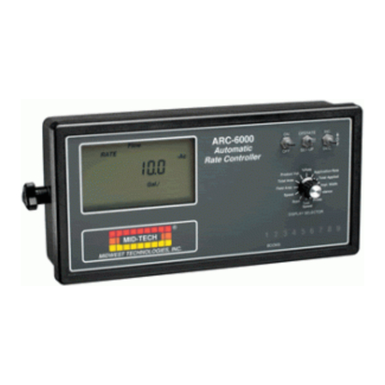
Distance turned off. Scan Prime Test Speed The ARC DISPLAY SELECTOR ¨ MID-TECH Control MIDWEST TECHNOLOGIES, INC. Console has BOOMS a nonvola- tile memory Fig. 1-1. ARC Console - that doesn’t require constant power to hold it’s Switches and Indicators information. -
Page 10: Display Selector Switch
Prime Prime Test Test Product Vol. Application Rate Speed Speed Total Area: DISPLAY SELECTOR DISPLAY SELECTOR ¨ Total Applied Total Area MID-TECH Accumulated Area. Field Area Impl.Width MIDWEST TECHNOLOGIES, INC. (Pg. 3-1)* Speed Distance BOOMS BOOMS Scan Prime Test Speed... -
Page 11: Functions - Setup Mode
Test display flashes Product Vol. Application Rate Speed Speed DISPLAY SELECTOR DISPLAY SELECTOR ¨ Total Applied Total Area and the console MID-TECH Field Area Impl.Width beeps each time MIDWEST TECHNOLOGIES, INC. Speed Distance BOOMS BOOMS a selected Scan Prime Test... -
Page 12: Status Switch
ARC-6000 Product Volume: Use the INC/DEC switch to set the full load value of the vehicle. (Pg. 2-14)** % Rate: The percent by which the programmed application rate can be changed with each activa- tion of the INC/DEC switch when application is underway. -
Page 13: Ground Speed Override
ARC-6000 Ground Speed Override Switch f your ARC system includes an optional MID- TECH® Boom Control Switch Box, the Ground Speed Override (GSO) switch is already installed. An optional, externally mounted, GSO switch can be used to temporarily operate the sprayer using a pre- Fig. - Page 14 ARC-6000 This page left blank intentionally 98-05012...
-
Page 15: English , Metric , Orm
ARC-6000 Chapter 2 Calibration NOTE: PLEASE READ THROUGH THE FOLLOW- ING SECTIONS COMPLETELY BEFORE YOU BEGIN CALIBRATION! he Control Console must be calibrated and pro- grammed with certain information before it can be used. First, the specific details of your applicator (i.e. -
Page 16: Setting Applicationr
NOTE: Metric to Metrish is not available. Change to English first and then to Metrish. Setting Application Rates Setting the APPLICA- he ARC 6000 system is designed to maintain a TION RATE to 0.0 will constant, pre-selected application rate. In order for turn off the flow the Control Console to do this, the operator must control function. -
Page 17: Setting The % Ratec
ARC-6000 Setting the % Rate Change his feature allows the operator to change the application rate “ ON THE GO” with a simple actuation of the INC/DEC switch. The amount of change each switch actuation makes is proportional to the value programmed into this position, (e.g. -
Page 18: Distance Calibration - G
ARC-6000 C. As each boom position appears on the display, use the INC/DEC Switch to set the display to the number of inches covered by that boom. Repeat for each Boom widths are section. entered in inches in the US system. For D. - Page 19 ARC-6000 Use the following initial calibration numbers. ® MID-TECH COMPACT RADAR - 780 Dj RADAR - 1000 WHEEL SENSOR - 3500 SPEEDOMETER SENSOR - 3500 To view and adjust the speed calibration number: A. Set the Control Console switches to the following...
- Page 20 ARC-6000 2. Set Mode Select switch to the “ SET- UP” mode. The console displays the current Distance Calibration Number. Record this number for future reference. As an example, assume this number is 1000. D. Drive the vehicle to the starting point of the mea- OPERATE INC.
- Page 21 ALIBRATION UMBER The following table gives calibration numbers for flow meters commonly found in MID-TECH systems. * For Raven flow meters use the factory calibration number divided by 10. For all other flow meters-use the manufacturers' supplied information regarding the pulses per gallon.
-
Page 22: Flow Meter Calibration
ARC-6000 UNING THE ETER ALIBRATION UMBER Once the initial calibration number is determined and entered into the console, run a calibration test to adjust the number for maximum accuracy. The accuracy of this test improves with the increase of both the volume of material discharged and the accuracy of measuring that volume. - Page 23 ARC-6000 F. Generate a speed input to the console. F-1d F-1b F-1c 1. Set the GSO Speed. OPERATE INC. SET- UP DEC. a) Turn the Display Selector to “ Speed” . % Rate Product Vol. Application Rate b) Select ‘SETUP” mode. Total Area Total Applied Field Area...
-
Page 24: Setting The Hold/Close R
ARC-6000 C. Write this number down for future reference. This is the number to use for these specific conditions (product and applicator configuration). Fine tuning of the calibration number can also be done based on field experience. If liquid is consistently left over after applying on a known number of acres, adjust the calibration number up slightly. -
Page 25: Setting The Test Speedv
ARC-6000 B. All Booms (or Master Switch) "OFF" MASTER C. Hold the INC/DEC switch up to display the current setting. Continuing to hold the INC Switch up causes the display to cycle between the two options at about three to ten second intervals. The option appearing in the display when the INC Switch is released is the response selected. -
Page 26: Setting The Grounds
ARC-6000 A. Set the Console to the following positions; 1. Power “ ON” OPERATE INC. 2. Mode Selector “ SETUP” SET- UP DEC. 3. Display Selector “ TEST SPEED” % Rate Product Vol. Application Rate Total Area Total Applied Field Area Impl. -
Page 27: Setting The Field Area
ARC-6000 Setting the Field Area Alarm he field area alarm alerts the operator, by flashing and beeping, as selected area amounts accumulate. The operator can use this feature as a reminder to check the load to verify that it is being dispensed at the correct rate. -
Page 28: Load Value )
ARC-6000 ECALLING THE ALUE When PRODUCT VOL. and OPERATE mode are selected, the Full Load Value of the vehicle can be recalled by holding the INC switch up for at least three seconds. ETTING A ALUE ESS THAN If a full load is not taken aboard the vehicle, the actual amount loaded can be set without changing the "Full Load Value". -
Page 29: Normal Start - Up Ando
ARC-6000 Chapter 3 Operation Normal Start-up and Operation t is important to verify that the control console is set up properly before beginning operations each day. Refer to Chapter 2 to review the detailed setup procedures. A. CONSTANTS: With all booms turned “ OFF” , verify that the proper distance, flow meter, and boom width constants are still entered in the console. -
Page 30: Changing Active Boom
Boom Section switches) is turned “ OFF” , the applica- MASTER tion stops. This allows the operator to select active AUTO MID-TECH MIDWEST TECHNOLOGIES, INC. boom sections “ ON THE GO” , while depending on the Fig. 3-1. Boom Section... - Page 31 Scan Prime Test Speed application rate by 2 X DISPLAY SELECTOR ¨ 20% or 40%. The MID-TECH MIDWEST TECHNOLOGIES, INC. 1 2 3 display shows 140%. BOOMS The flow control valve opens until the Fig. 3-2. Changing App. flowmeter measures 14.0 gallons per acre. None of the Rate “...
-
Page 32: Priming The Main Pump And Ground Speed Override
ARC-6000 Priming the Main Pump and Boom se the following procedure to “ PRIME” the main pump and boom lines prior to spraying. A. Set the console switches to the following posi- tions: 1. Power “ ON” 2. Mode Selector “... - Page 33 ARC-6000 When the GSO Switch is "ON" (closed), and the actual ground speed is less than the "GSO Speed", the ARC automatically uses the "GSO Speed" value to control the application rate. If the actual ground speed in- creases above the preset "GSO Speed", the control console will revert to controlling application rate on the basis of the actual ground speed.
- Page 34 ARC-6000 This page left blank intentionally 98-05012...
-
Page 35: Flushing And Cleaning
Keeping the equip- ment clean also makes it As a general rule, MID-TECH recommends the easier to maintain the following. Do not leave chemical or chemical solu- vehicle and extends its tions in the applicator overnight. The system should be working life. -
Page 36: Ground Speed Sensor
SENSOR, PARTICULARLY IN COLD WEATHER, AS DAMAGE TO THE MECHA- NISM MAY OCCUR. The impeller type flow meters supplied by MID-TECH are inherently rugged. However, continued use eventually wears the internal bearings and shafts causing the meter to be inaccurate. Replacement kits... -
Page 37: Wiring Harness
NISM MAY OCCUR. Wiring Harness ost failures of electronic systems, like the MID-TECH Control System, are the result of broken wires or poor connections. Taking some time to periodically inspect and clean the wiring harness and connectors will help prevent these types of failures. - Page 38 NOTICE: A Returned Material Authorization Number (RMA #) must be obtained from MID-TECH or your dealer for all items returned to MID-TECH for repair or replacement. MID-TECH product(s) returned for repair or...
-
Page 39: Chapter 5 Troubles
ARC-6000 Chapter 5 Trouble Shooting - Error Messages Trouble shooting of the MIDWEST TECHNOLOGIES Control System begins when the Control Console senses a problem or inconsistency in the system. When this happens, the Control Console alerts the operator with a visual and audible alarm. - Page 40 Pump L (Cont.) Pressure LOW, main strainer; Pressure HIGH, nozzle screens. Not a diagnostic function in Contact your MID-TECH Err 2 dealer if you see this the ARC console. message on an ARC control- ler. Console is not receiving Err 3 pulses from the flow meter.
- Page 41 Control” port on back of console, to flowmeter for bad connections, abrasions, and pinched or broken wires. Err 4 Contact your MID-TECH Not a diagnostic function in dealer if you see this message the ARC. on an ARC controller. Err 5 Check “...
- Page 42 ARC-6000 Hold down the decrease Err E Memory error. switch until the alarm stops. Check for any constants that This is often the result of a may have been set to zero poor battery connection. and re-enter the correct values. (See Chapter 2) Hold down the decrease Value to be displayed on OFLO...
-
Page 43: Display Selector
5.0 of this manual. Assuming there is no success in getting the failed component to respond, MID-TECH suggests the following procedures, as a temporary measure, until the component can be repaired or replaced. -
Page 44: Flow Control Valvef
If the vehicle is traveling faster or slower than the established GSO speed, the system will be over or under applying accordingly. MID-TECH recom- mends this procedure as F. The console still records the Total Applied, and the a temporary, emergency system still adjusts to changes in boom width. - Page 45 At this point, the operator is enjoying some monitoring functions of the ARC, but has no positive control of the flow control valve. MID-TECH recom- E. Monitor APPLICATION RATE. Actual application mends this procedure as rate is displayed. Adjust the ground speed to a temporary, emergency maintain the desired rate.
-
Page 46: Flowmeter Failure
DEC switch on the control console. INC will open the flow control valve and DEC will close the valve. MASTER ¨ 4. Once the desired pressure is attained, turn all AUTO MID-TECH MIDWEST TECHNOLOGIES, INC. boom sections “ OFF” . 98-05012... - Page 47 INC/ DEC switch. Areas accumulate normally. Speed reads correctly. MID-TECH recommends this procedure as a temporary, emergency procedure only. The prob- lem should be resolved as soon as possible to allow full automatic control of the sprayer to be reestab- lished.
- Page 48 ARC-6000 This page left blank intentionally 98-05012...
-
Page 49: Appendixa - Systemd
ARC-6000 Appendix A - System Diagrams Appendix A System Diagrams 98-05012... - Page 50 ARC-6000 Fig. A 1. ARC Flow Control - Wiring Diagram 98-05012...
- Page 51 ARC-6000 Fig. A 2. ARC Flow Control - Plumbing Diagram 98-05012...
-
Page 52: Rate
ARC-6000 VALUES DISPLAYED BY ARC-6000 FILL OUT BEFORE CALLING FOR FASTER SERVICE SOFTWARE VERSION: ____________________ Number displayed when console first powers up; e.g. 1.31 MODE SWITCH SETTING OPERATE SET-UP FIELD AREA TOTAL AREA PRODUCT VOL. % RATE APPLICATION RATE TOTAL APPLIED IMPL. - Page 53 ARC-6000 Appendix B - System Overview Appendix B System Overview 98-05012...
-
Page 54: Appendixb - Systemo
Total Applied Field Area Impl. Width Speed Distance Scan Prime Test Speed DISPLAY SELECTOR ¨ MID-TECH 1 2 3 4 5 6 7 8 9 MIDWEST TECHNOLOGIES, INC. BOOMS Rate Change Application Rate Commands Data Boom Width Data Fig. B-1 ARC... -
Page 55: Ig . B-2. Arc 6000 Console
ARC-6000 1. The ARC System Control Console The ARC 6000 Control Console is the heart of the system and actually performs three separate functions. ARC-6000 OPERATE INC. Flow Automatic RATE Rate Controller SET- UP DEC. Gal./ %Rate Product Vol. Application Rate... - Page 56 ARC-6000 An optional radar ground speed sensor is available from MID-TECH for applications where wheel slippage and variations in ground conditions are a concern. The radar sensor does not depend on ground contact and is therefore unaffected by these problems.
-
Page 57: Switchbox
If the valve meets the speed and precision requirements of the ARC system, it can usually be adapted for use. Check ® with your MID-TECH dealer, or the factory, about the adaptability of a specific valve. 5. Boom Interface... - Page 58 ARC-6000 This page left blank intentionally 98-05012...
- Page 59 ARC-6000 Appendix C - Glossary/Tables Appendix C Glossary/Tables 98-05012...
- Page 60 ARC-6000 Glossary The definitions in this glossary are worded to fit the needs of this manual only and may not apply to all sprayer operations in general. AutoRange® Valve - A three port valve which controls both the main liquid flow and bypass flow. Boom - An application width that is assigned a value and is used to calculate area.
- Page 61 This system is designed to control product to a target rate. Flowmeter - A device which measures volumetric liquid flow. MID-TECH uses two different basic types of flowmeter. Standard Flowmeters - Each standard flowmeter has a standard range that it caaccurately measure. To change ranges requires changing flowmeters.
- Page 62 ARC-6000 to be sent to the control console. Implement Status Switch - Provides a another means to stop the spraying operation. This switch may take the form of a foot swich or an implement switch mounted on the toolbar that opens a circuit as the tool bar is raised, effectively stopping the spraying operation..
- Page 63 MID-TECH or your dealer, which serves as your approval to return the item and informs MID-TECH of the circumstances of the return so that proper action (repair, replacement, credit, etc.) can be initiated quickly upon receit of the item at MID-TECH.
-
Page 64: Seful Ormulas
ARC-6000 SEFUL ORMULAS (Rate x Speed x Noz. Spacing) Noz. Press. = (GPM x 939.2) Where: Rate = GPA Speed = MPH Noz. Spacing = Inches = Noz. Flow @ 40 PSI [GPM x 939.2 x (P Min = (Noz. Spacing x GPA) (GPM x 2970) Where: GSO... -
Page 65: English/Metric Conversion
ARC-6000 English/Metric Conversion U.S. to Metric 1 Acre = 0.405 Hectares 1 mile = 1.61 Kilometers 1 Foot = 0.305 Meters 1 Inch = 2.54 Centimeters 1 US Gallon = 3.785 Liters 1 Fluid Ounce = 29.57 Milliliters 1 pound = 0.454 Kilogram 1 Cubic Foot (ft ) = 0.028 Cubic Meters (M 1 Pound per Gallon = 119.68 Grams per Liter... -
Page 66: Iscellaneous Otes
ARC-6000 ALIBRATION UMBERS Booms: 1. _____ 3. _____ 5. _____ 7. _____ 9. _____ 2. _____ 4. _____ 6. _____ 8. _____ C. _____ : _______ ISTANCE : _______ ETER ISCELLANEOUS OTES 98-05012... - Page 67 For products that come in direct contact with chemical, the specific recommen- dations contained in Mid-Tech product bulletins must be adhered to, or this warranty is void. Any repairs or alter- ations, other than those provided by Mid-Tech and/or its authorized representatives, will void the warranty. Mid-Tech neither assumes nor authorizes anyone to assume for it any other obligation or liability in connection with said product.
- Page 68 MIDWEST TECHNOLOGIES ILLINOIS, LLC Specialists in Control System Electronics Since 1983 Contact your Mid-Tech dealer to see our complete line of accessories for your ap- plication Corporate Office Montana Office Sales and Service 2733 East Ash Street 90 West Central Avenue www.mid-tech.com...
Need help?
Do you have a question about the ARC 6000 and is the answer not in the manual?
Questions and answers