Table of Contents
Advertisement
Quick Links
99 Washington Street
Melrose, MA 02176
Phone 781-665-1400
Toll Free 1-800-517-8431
Visit us at www.TestEquipmentDepot.com
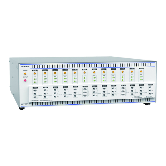
SS7081-50
BATTERY CELL VOLTAGE
GENERATOR
Be sure to read this manual before using the instrument.
When using the instrument for the
first time
Name and Function of Each Part
Preparation Process
Apr. 2020 Edition 1
SS7081C961-00 20-04H
Troubleshooting
p.6
Maintenance and Service
p.11
Error Display
HIOKI SS7081C961-00
Instruction Manual
p.2
p.61
p.61
EN
Advertisement
Table of Contents

Related Manuals for Hioki SS7081-50

Summary of Contents for Hioki SS7081-50
- Page 1 99 Washington Street Melrose, MA 02176 Phone 781-665-1400 Toll Free 1-800-517-8431 Visit us at www.TestEquipmentDepot.com SS7081-50 Instruction Manual BATTERY CELL VOLTAGE GENERATOR Be sure to read this manual before using the instrument. p.2 When using the instrument for the...
-
Page 2: Table Of Contents
Abnormal temperature inside the case ..................... 28 Communication Command ........................29 5.1 Commands Overview ..........................29 Message format............................29 Output queue and input buffer ........................32 Status byte registers ........................... 32 Event registers ............................. 33 Communications errors ..........................36 HIOKI SS7081C961-00 SS7081C961-00... - Page 3 Cleaning ................................ 61 7.1 Error Display ............................61 License Information ..........................63 Appendix ................................65 Appx. 1 Internal Circuit Configuration ...................... 65 Appx. 2 Dimensions Diagram ........................66 Appx. 3 Mounting the Instrument in the Rack ..................67 HIOKI SS7081C961-00...
-
Page 4: Introduction
It is assumed that the reader possesses basic electrical knowledge (equivalent to that of someone who graduated from the electrical program at a technical high school). Accuracy Hioki defines measurement accuracy in terms of percentages of the setting, the full scale, and the reading and digits. Set value... -
Page 5: Safety Information
Indicates the Waste Electrical and Electronic Equipment Directive (WEEE Directive) in EU member states. Indicates that the product conforms to regulations required by the EU Directive. Other Symbols Additional information is presented below. (p. ) HIOKI SS7081C961-00 Indicates the location of reference information. -
Page 6: Usage Notes
Handling the cables CAUTION • Avoid stepping on or pinching the cable, which could damage the cable insulation. • To prevent damage due to snapped wires, do not bend or pull the cables. HIOKI SS7081C961-00... - Page 7 HIOKI SS7081C961-00...
-
Page 8: Overview
The instrument can simulate wire breaks in cables between the battery and BMS board as well as cell short- circuits. Safety functionality In the event a BMS board malfunction causes an abnormal current to flow, the instrument can stop output to prevent damage to the circuit under test. HIOKI SS7081C961-00... -
Page 9: Name And Function Of Each Part
I terminal: Connects the voltage source in series. Connects the instrument board reference potential output terminal. O terminal: Connects to the other unit of Model SS7081-50 output terminal. RY terminal: Connects to the measuring object or the other unit of Model SS7081-50 output terminal. - Page 10 (next two digits). Do not remove this sticker as the number is important. Main power switch Turns on and off the instrument. Reference: “2.6 Turning the Instrument On and Off” (p. 17) Vent (Fan) Install the instrument so as not to block the vents. HIOKI SS7081C961-00...
-
Page 11: Lamp Display
For details, see “3.2 Switching Output Terminals” (p. 21). Other (error display) If the ALERT lamps for all channels light up, or the ERROR lamp flashes, the instrument has experienced a malfunction. For details, see “7.1 Error Display” (p. 61). HIOKI SS7081C961-00... -
Page 12: Control Methods
The instrument interface is an Ethernet 100BASE-TX. If using a 10BASE-T or 100BASE-TX-compatible LAN cable (30 m max.) to connect to a communications command port using TCP, the instrument can be controlled using communications commands. If controlling multiple instruments, each one is controlled independently. There is no master/subordinate relationship. HIOKI SS7081C961-00... - Page 13 HIOKI SS7081C961-00...
-
Page 14: Preparations
Connect the power cord to the instrument power supply inlet. Connect the power cord to the outlet. If power interrupts (a breaker tripped, etc.) while the instrument is on, the instrument will automatically start once the power supply is restored next time. HIOKI SS7081C961-00... -
Page 15: Connecting The Output Cable
When using wiring whose insulation has a low insulation resistance, the wire’s leakage current may affect the accuracy of minuscule current measurement. • When using the 100 μA range, it is recommend to use cables with either polyethylene (PE) or polytetrafluoroethylene (PTFE) insulation. HIOKI SS7081C961-00... -
Page 16: Connecting Channels
Connecting channels You can connect the channels and multiple units of Model SS7081-50 in series. When connecting CH 1 to the cell with the highest potential CH 1 CH 2 Connect the negative terminal to the C terminal. Connect the... -
Page 17: Connecting Multiple Instruments
C terminal of the instrument on the low-potential side. Note: If it is not necessary to disconnect the instruments, connect the terminal to the CHAIN O terminal. 20-channel connection example Measuring object For the output terminals, see “3.2 Switching Output Terminals” (p. 21). HIOKI SS7081C961-00... -
Page 18: Setting The Ip Address
IP address of the device that becomes a gateway. The instrument does not have a default gateway setting. Specify the connected TCP/IP port number for communication Communication commands. command port number The instrument’s communication command port number is permanently set to 1024. HIOKI SS7081C961-00... -
Page 19: Connecting The Lan Cable
Make the network settings of the computer. Make the TCP/IPv4 settings of the computer to be connected to the instrument as follows. IP address: 192.168.1.X* Subnet mask: 255.255.255.0 Default gateway: None *: Set X to a different value than the instrument. HIOKI SS7081C961-00... -
Page 20: Turning The Instrument On And Off
If power interruptes (a breaker tripped, etc.) while the instrument is on, the instrument will automatically start once the power supply is restored next time. Settings are not backed up. When the instrument is turned on, all settings are at their default values. For the default values, see “Initialize the instrumen” (p. 40). HIOKI SS7081C961-00... - Page 21 HIOKI SS7081C961-00...
-
Page 22: Generation And Measurement
Stopping voltage output Configure the setting to turn output off. Issue a command to set the output terminal. Reference: “3.2 Switching Output Terminals” (p. 21) Reference: Communication command “Output voltage” (p. 46) HIOKI SS7081C961-00... -
Page 23: Changing The Output Voltage At High-Speed (Memory Output Function)
(:SOURce:VOLTage:MEMory:STATe ON,<Channel number>) IMPORTANT When connecting a capacitive load, output may not reach the set voltage within the set amount of time. Stopping memory output Stop memory output. (:SOURce:VOLTage:MEMory:STATe OFF,<Channel number>) Reference: Communication command “Memory outputs” (p. 47) HIOKI SS7081C961-00... -
Page 24: Switching Output Terminals
Generation The set voltage circuit will be output. C terminal Positive terminal: (Red) The positive Positive terminal terminal will be disconnected from Negative the instrument’s terminal internal circuitry, placing it in an undefined state. C: Lit Positive: Unlit HIOKI SS7081C961-00... - Page 25 C terminal : (White) The C terminal will be shorted Generation with the negative terminal. circuit C terminal Positive terminal : The positive terminal will be Positive shorted with the negative teminal terminal. Negative terminal C: Unlit Positive: Unlit HIOKI SS7081C961-00...
-
Page 26: Output Expansion Terminal (Chain Terminal)
O terminal RY terminal: Connects the terminal to I terminal RY terminal and O terminal I terminal RY terminal: O terminal Disconnects the terminal from the instrument’s internal circuitry and RY terminal places it in an open state. HIOKI SS7081C961-00... -
Page 27: Voltage And Current Measurements
• When using wiring whose insulation has a low insulation resistance, the wire’s leakage current may affect the accuracy of minuscule current measurement. When using the 100 μA range, it is recommend to use cables with either polyethylene (PE) or polytetrafluoroethylene (PTFE) insulation. Reference: Communication command “Current measurement range” (p. 48) HIOKI SS7081C961-00... -
Page 28: Acquiring Stable Measured Values (Smoothing Function)
When changing other settings, wait [smoothing count × 1 PLC + 3] ms before querying the voltage and current value. Disabling the smoothing function Disable the smoothing function. (:[SENSe]:AVERage:STATe 0,<Channel number>) Reference: Communication command “Smoothing function” (p. 48) HIOKI SS7081C961-00... -
Page 29: Saving, Collating, And Acquiring Measured Values (Logging Function)
:DATA:STATe 0 Loading logging data Output voltage logging data. (:DATA:VOLTage? <Channel number>,<Date count>) Output current logging data. (:DATA:CURRent? <Channel number>,<Date count>) If no data count is specified, all data will be returned. Reference: Communication command “Logging” (p. 49) HIOKI SS7081C961-00... -
Page 30: Error Detection Function
For the set disabled time after the instrument is switched from the 100 μA range to the 1 A range (default value: 1 s) • 0.1 s after switching from the 1 A range to the 100 µA range (Changes can be made using communications commands) HIOKI SS7081C961-00... -
Page 31: Abnormal Temperature Inside The Case
Are the instrument’s vents blocked? Verify that the instrument’s vents are not blocked. Has the internal temperature error Set an appropriate threshold. detection function’s threshold been set appropriately? Reference: Communications Commands “Self-diagnosis” (p. 50) HIOKI SS7081C961-00... -
Page 32: Communication Command
Messages include program messages sent to the instrument from the controller such as a PC, etc., and response messages sent to the controller from the instrument. Program message Controller SS7081-50 Response message Message types are further categorized as follows. Command message... - Page 33 (2) Header separators In a message consisting of both a header and data, the header is separated from the data by a space “ ” (ASCII code 20H). :OUTPut:ON:MODE NORMal HIOKI SS7081C961-00...
- Page 34 A colon “:” is not required at the start of the header of a simple or compound command. However, to avoid confusion with abbreviated forms and operating mistakes, Hioki recommend always placing a colon at the HIOKI SS7081C961-00...
-
Page 35: Output Queue And Input Buffer
Service Request Enable Register. When any bit selected by the mask is set, bit 6 (MSS; Master Summary Status bit) of the Status Byte Register is also set. HIOKI SS7081C961-00... -
Page 36: Event Registers
Execution error 実行エラー bit4 <16> Command error コマンドエラー bit5 <32> bit6 <64> Power-on 電源ON bit7 <128> *ESR? When 1 is set for each bit, the status is 各ビットに1がセットされると、クエリを受けて retained until the query result is returned. 結果を返すまでその状態は保持されます。 *ESE *ESE? HIOKI SS7081C961-00... - Page 37 Not used by the instrument. Bit 1 (Unused) Request control Operation complete • When an “ *OPC ” command is executed Bit 0 • When operations of all messages up to an “ *OPC ” command are completed HIOKI SS7081C961-00...
- Page 38 Measurement error Bit 6 MEAS_ERR4 Bit 5 VOLT_ERR Output voltage error Bit 4 CRR_ERR Overcurrent error Bit 3 FRQ_ERR Power supply frequency error Bit 2 TEMP_ERR Temperature error Bit 1 FAN_ERR Fan stop Bit 0 HW_ERR Hardware error HIOKI SS7081C961-00...
-
Page 39: Communications Errors
If the command or clear data format is incorrect • Query error If the controller cannot receive, or if the instrument cannot send response messages • Execution error If other than the designated character data or numerical data has been set HIOKI SS7081C961-00... -
Page 40: Message List
Queries the current measurement range. (+1.00000E-04/+1.00000E+00) Reading measurement data [<Channel number 1 to 12> ]* :FETCh:VOLTage? Queries the voltage measured value. (Voltage measured value) [<Channel number 1 to 12> ]* :FETCh:CURRent? Queries the current measured value. (Current measured value) HIOKI SS7081C961-00... - Page 41 Line Frequency :SYSTem:LFRequency? (50/60) Queries the commercial power supply frequency. Communication settings :SYSTem[:COMMunicate:LAN]:MAC? (MAC address) Queries the MAC address. If the parameters of the channel number are ommitted, all channels data will be responded as separated by "," (comma). HIOKI SS7081C961-00...
-
Page 42: Message Reference
Sets channel 1 to 2.5 V. Shows an example of an :VOLT 3.5 Sets all 12 channels to 3.5 V. actual command application. :VOLT? 1 3.5000 The channel 1 output voltage is set to 3.5 V. Command, query Controller SS7081-50 Response HIOKI SS7081C961-00... -
Page 43: Standard Commands
Standard commands (1) System data command Query the instrument version Syntax *IDN? Query Response <Manufacturer name>,<Model name>,<Serial No.>,<Software version> Example IDN? HIOKI,SS7081-50,123456789,V2.00 Returns the model version. (2) Internal operation commands Initialize the instrument Syntax Command *RST Description Command Initializes the instrument. -
Page 44: Synchronized Commands
1 bit 0 PON URQ CME EXE DDE QYE RQC OPC Since bit 0 and bit 6 are not used, they are always 0. Example * ESE 36 Sets bit 5 and bit 2 of the SESER. HIOKI SS7081C961-00... - Page 45 Returns the set contents of the STB using a NR1 numerical value from 0 to 255. bit 7 bit 6 bit 5 bit 4 bit 3 bit 2 bit 1 bit 0 ESB0 Example * STB? Bit 4 of the STB has been set to 1. HIOKI SS7081C961-00...
-
Page 46: Instrument-Specific Commands
Note • When the power is turned on, the data is initialized to 0. • When 1 is set for an unused bit (expressed by -), a command is accepted, but it does not affect the query result. HIOKI SS7081C961-00... -
Page 47: Reading The Measured Value
(2) Reading the measured value The query response that returns the measured value has the format shown below. Format of the measured value Measured value ±OvrRng is displayed Measurement error occurs ± □.□□□□□E±□□ ±9.00000E+34 +9.10000E+34 HIOKI SS7081C961-00... -
Page 48: Output Terminals
<1/0/ON/OFF> :OUTPut: CHAin[:STATe]? Query Response <1/0(NR1)> Description Sets or queries the ON/OFF of the output expansion terminal (RY terminal). Example :OUTP: CHA 1 Enables the output expansion terminal. :OUTP: CHA? The output expansion terminal is set to ON. HIOKI SS7081C961-00... -
Page 49: Output Voltage
Channel 1 is set to 3.5 V and channel 2 is set to 3.4 V. ••• (In the same manner, each channel is set to a specified voltage.) :VOLT? 1 +2.50000E+00 The channel 1 output voltage is set to 2.5 V. HIOKI SS7081C961-00... -
Page 50: Memory Outputs
Attempting to start during memory outputs will cause an execution error. Query: Returns 0 during memory output stop. Returns 1 during memory outputs. Example :VOLT: MEM: STAT 1,1 Starts the memory outputs for channel 1. :VOLT: MEM: STAT? 1 Channel 1 is performing the memory outputs. HIOKI SS7081C961-00... -
Page 51: Current Measurement Range
Example :AVER 1,1 Makes the setting so that channel 1 performs the smoothing. :AVER 1 Makes the setting so that all 12 channels perform the smoothing. :AVER? 1 The setting is made so that channel 1 performs smoothing. HIOKI SS7081C961-00... -
Page 52: Logging
• If the number of read data points is greater than the number of data points saved • If no saved data is found Do not issue commands or queries while data is being transferred. To cancel a data transfer, execute *CLS. Example :DATA: VOLT? 1,10 +4.20001E+00,+4.19999E+00•••+4.20000E+00 HIOKI SS7081C961-00... -
Page 53: Self-Diagnosis
:VOLT: TLIM 45,AMP Sets 45°C for the temperature error threshold value of the output board. :VOLT: TLIM? AMP The threshold value of the output board that gives a warning of the temperature error has been set to 45°C. HIOKI SS7081C961-00... -
Page 54: Commercial Power Supply Frequency
The commercial power supply frequency is 60 Hz. (12) Communication settings Query the MAC address Syntax :SYSTem[:COMMunicate:LAN]:MAC? Query Response <MAC address> Description Returns the MAC address of the instrument. Example :SYST:COMM:LAN:MAC? “00-01-67-07-03-85” The instrument MAC address is 00-01-67-07-03-85. HIOKI SS7081C961-00... -
Page 55: Command Examples
AVER:COUN 100 Set the averaging count to 100 for all channels. VOLT 3.3 Set all channels to 3.3 V. OUTP ON Set the output terminal to ON. FETC:CURR? Acquire the measured current for all channels. +3.00000E-10,+7.00000E-10,+5.00000E-10, +4.00000E-10,+7.00000E-10,+5.00000E-10, +6.00000E-10,+3.00000E-10,+4.00000E-10, +5.00000E-10,+6.00000E-10,+4.00000E-10 HIOKI SS7081C961-00... -
Page 56: Enable The Logging Function And Acquire Current Values Using The 100 Μa Range
Set all channels to 3.3 V. DATA:STAT 1 Start logging. DATA:STAT 0 Stop logging. DATA:POIN? 1 Query the logging data count. DATA:CURR? 1 Acquire logged current values for channel 1. +2.00000E-10,+2.00000E-10,+2.00000E-10,+3.00000E-10 DATA:VOLT? 1 Acquire logged voltage values for channel 1. +3.30003E+00,+3.30003E+00,+3.30003E+00,+3.30003E+00 HIOKI SS7081C961-00... - Page 57 HIOKI SS7081C961-00...
-
Page 58: Specifications
LED (ERROR, OUTPUT, ALERT×12, RUN_C×12, RUN_ positive×12) Switch Power switch, IP address assigning switch Interface Approx. 430W × 132H × 483D mm (16.93″W× 5.20″D × 19.02″H) (excluding Dimensions protrusions) Mass Approx. 10.3 kg (363.3 oz.) Product 1 year warranty period Accessories Reference: “Accessories” (p.1) HIOKI SS7081C961-00... -
Page 59: Specifications Of Input, Output, And Measurement
NMRR With power supply frequency set to ±1%: 35 dB or more With power supply frequency set to ±0.1%: 55 dB Current or more NMRR measurement With power supply frequency set to ±1%: 35 dB or HIOKI SS7081C961-00 more... - Page 60 1000 pF or less for each channel ground Accuracy specifications Guaranteed accuracy period: 1 year Guaranteed accuracy period from adjustment made by Hioki: 1 year Conditions of Accuracy guarantee temperature and humidity range: 23°C±5°C (73°F±9°F), guaranteed 80% RH or less...
-
Page 61: Specifications Of Functions
ZERO: Positive and C terminals shorted to circuit ground ON (NORMAL/HIGH IMPEDANCE/ZERO) Settings OFF (HIGH IMPEDANCE/ZERO) Default setting OFF (NORMAL when ON, ZERO when OFF) Output Setting ON/OFF expansion terminal (CHAIN terminal) Default setting ON switching HIOKI SS7081C961-00... - Page 62 16 sensors. detection Output board threshold: 30°C to 80°C Settings Control board threshold: 30°C to 80°C Default Output boards: 70°C values Control board: 50°C Reset Resets all settings to the factory defaults. HIOKI SS7081C961-00...
-
Page 63: Interface Specifications
Configuration, equipment status acquisition, settings acquisition Communications via communication commands IP address: 192.168.1.xxx (only the “xxx” portion can be changed) Settings Subnet mask: 255.255.255.0 (fixed) Default gateway: None (fixed) Communications command port: 1024 (fixed) Default setting IP address: 192.168.1.1 HIOKI SS7081C961-00... -
Page 64: Maintenance And Service
• If shipping without using the packing boxes and buffer material from the time of purchase, and the product is damaged, please note that Hioki cannot be responsible for any repair costs even if still within the warranty period. •... - Page 65 HIOKI SS7081C961-00...
-
Page 66: License Information
OR BUSINESS INTERRUPTION) HOWEVER CAUSED AND ON ANY THEORY OF LIABILITY, WHETHER IN CONTRACT, STRICT LIABILITY, OR TORT (INCLUDING NEGLIGENCE OR OTHERWISE) ARISING IN ANY WAY OUT OF THE USE OF THIS SOFTWARE, EVEN IF ADVISED OF THE POSSIBILITY OF SUCH DAMAGE. HIOKI SS7081C961-00... - Page 67 HIOKI SS7081C961-00...
-
Page 68: Appendix
“3.2 Switching Output Terminals (p. 21)”. A wide input switching power supply of 100 V to 240 V is used in the power supplier to enable stable measurements even in an environment where the power supply is unstable. HIOKI SS7081C961-00... -
Page 69: Appx. 2 Dimensions Diagram
Appx. 2 Dimensions Diagram 57.1 (Unit: mm) HIOKI SS7081C961-00... -
Page 70: Appx. 3 Mounting The Instrument In The Rack
• If removing the instrument from a stand and restoring the original configuration, use the same screws as were used for the original mounting. (M3 × 8 mm) If you have lost a screw or find that a screw is damaged, please contact your authorized Hioki distributor or reseller. - Page 71 Test Equipment Depot - 800.517.8431 - 99 Washington Street Melrose, MA 02176 HIOKI SS7081C961-00 TestEquipmentDepot.com...
Need help?
Do you have a question about the SS7081-50 and is the answer not in the manual?
Questions and answers