Table of Contents
Advertisement
Quick Links
Advertisement
Table of Contents

Summary of Contents for XPR Access BIOC3 V1
- Page 1 BIOC3 V1 Biometric Reader USER’S MANUAL www.xprgroup.com...
-
Page 2: Table Of Contents
Contents 1. DESCRIPTION 2. SPECIFICATIONS 3. MOUNTING 4. WIRING 5. CONNECTING BIOMETRIC READERS TO EWS CONTROLLER 5.1 CONNECTING BIOMETRIC READERS IN SAME RS485 LINE WITH THE EWS CONTROLLERS 5.2 CONNECTING BIOMETRIC READERS WHEN ALL THE CONTROLLERS HAVE TCP/IP COMMUNICATION 6. CONNECTING BIOMETRIC READERS TO 3RD PARTY CONTROLLER 6.1 CONVERTERS PIN DESCRIPTION 7. -
Page 3: Description
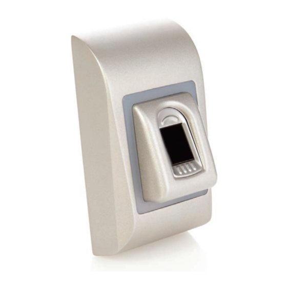
1. DESCRIPTION BIOC3 is a Wiegand biometric reader for indoors access control applications. It o ers storage up to 9500 ingerprints and programmable Wiegand Output (8 to 128 bits). Con iguration of the readers and ingerprint enrollment is done through PC Software. Connection between the biometric readers is RS485 and it is used for ingerprint transfer and con iguration. -
Page 4: Wiring
4. WIRING 5. CONNECTING BIOMETRIC READERS TO EWS CONTROLLER - The Biometric readers can be connected to virtually any controller that conforms to Wiegand format standards (standard Wiegand 26bit or self-de ined Wiegand). - The lines D0 and D1 are the Wiegand lines and the Wiegand Number is sent through them. - The RS485 line (A, B) is used for ingerprint transfer and reader settings. -
Page 5: Connecting Biometric Readers In Same Rs485 Line With The Ews Controllers
5.1 CONNECTING BIOMETRIC READERS IN SAME RS485 LINE WITH THE EWS CONTROLLERS • The Biometric readers are connected through RS485 bus. The same RS485 bus that the EWS controllers are connected to. • Maximum units in one network (EWS + Biometric readers) is 32. •... -
Page 6: Connecting Biometric Readers To 3Rd Party Controller
6. CONNECTING BIOMETRIC READERS TO THIRD PARTY CONTROLLERS BIOPROX USB USB DESKTOP READER OPTIONAL • Connect the lines D0, D1, Gnd and +12V to the third party controller. • Connect the RS485 Line (A, B) to the converter. Connect the converter in the PC. •... -
Page 7: Enrollment
7. ENROLLMENT 8. CONFIGURING THE BIOMETRIC READERS IN PROS CS SOFTWARE 8.1 ADDING BIOMETRIC READER 1. Expand the Door item to view the readers 2. Right click on the reader and select properties (8.1) 3. In the Basic tab, for “Type” of the Reader select “BIOC3”. (8.2) 4. -
Page 8: Enrolling Fingerprints From A Reader
8.2 ENROLLING FINGERPRINTS FROM A READER 1. Open the Users Window and create a new user. Click on “New User”, put a name and ID(card number). (8.7) 2. Go to the “Biometric” Tab 3. Select the reader(with left click) from which the enrollment will be done. (8.8) 4. -
Page 9: Enrolling Fingerprints From Desktop Reader
8.3 ENROLLING FINGERPRINTS FROM DESKTOP READER Plug the Desktop Reader in the PC. It is installed in the same way as a USB Device. When the desktop reader has been installed it will automatically appear in the Software. (8.13) 1. Open the Users Window and create a new user. Click on “New User”, put a name and ID(card number). -
Page 10: Deleting Fingerprints
8.4 DELETING FINGERPRINTS In General, the ingerprints are stored in the Biometric reader and in the Software. Deleting can be done only in the readers or from both places. Deleting one user from the biometric reader Select the User Click on “Delete User”. The User together with its ingerprints will be deleted from both the software and the ingerprint readers. -
Page 11: Firmware Update
8.6 FIRMWARE UPDATE Right-click on the reader and select Firmware update menu (8.18) On the Firmware update window, click on the Browse button (8.19). The default location of the irmware iles installed with PROS CS is in the folder “Firmware”. Select the irmware ile with a “xhc”... -
Page 12: Configuring The Biometric Readers In Biomanager
9. CONFIGURING THE BIOMETRIC READERS IN BIOMANAGER CS BIOMANAGER CS is software for ingerprint management of XPR Biometric readers, when used with third party access controllers. Main functions: - Fingerprint Enrollment It can be done by ANY Biometric reader in the network or by Desktop (USB) Biometric reader. - Fingerprint Transfer Finger templates can be sent to any Reader in the Network. -
Page 13: Edit Reader
If reader is online, new line is added on top of the event table If reader is not online, following line is added on top of the event table If reader is online, right click on reader and select Upload con iguration Check at event table if con iguration was successful 9.3 EDIT READER Right-click on the reader and select Properties... -
Page 14: Add User
9.5 ADD USER 1. Open the Users Window and create a new user. Click on “New User”, put a name, ID(card number). (8.7) 2. Go to the “Biometric” Tab 3. Select the reader(with left click) from which the enrollment will be done. (8.8) 4. -
Page 15: Uploading The Fingerprints To The Biometric Readers9.12 Custom Wiegand
9.6 DELETING FINGERPRINTS In General, the ingerprints are stored in the Biometric reader and in the Software. Deleting can be done only in the readers or from both places. Deleting one user from the biometric reader Select the User Click on “Delete User”. The User together with its ingerprints will be deleted from both the software and the ingerprint readers. (8.14) Deleting all users from the biometric reader Right click on the reader and select “Delete all users from reader”... -
Page 16: Custom Wiegand
9.8 CUSTOM WIEGAND BIOMANAGER CS has de ined Wiegand 26, 30, 34, 40 bit as standard options and other 3 Wiegand settings as user de inable. To setup custom Wiegand format Select Wiegand menu from Settings At Wiegand setup window select one from customs Wiegand Set Wiegand parameter Click on Save button Wiegand settings are out of scope for common end user. -
Page 17: Wiegand Protocol Description
10. WIEGAND PROTOCOL DESCRIPTION The data is sent over the lines DATA 0 for the logic “0” and DATA 1 for the logic “1”. Both lines use inverted logic, meaning that a pulse low on DATA 0 indicates a “0” and a pulse low on DATA 1 indicates a “1”.When the lines are high, no data is being sent. Only 1 of the 2 lines ( DATA 0 / DATA 1 ) can pulse at the same time. -
Page 18: Safety Precautions
11. SAFETY PRECAUTIONS Do not install the device in a place subject to direct sun light without protective cover. Do not install the device and cabling close to a source of strong electro-magnetic ields like radio-transmitting antenna. Do not place the device near or above heating equipments. If cleaning, do not spray or splash water or other cleaning liquids but wipe it out with smooth cloth or towel. - Page 19 www.xprgroup.com...
- Page 20 This product herewith complies with requirements of EMC directive 2014/30/EU. In addition it complies with RoHS2 directive EN50581:2012 www.xprgroup.com...
Need help?
Do you have a question about the BIOC3 V1 and is the answer not in the manual?
Questions and answers