Table of Contents
Advertisement
Advertisement
Table of Contents

Related Manuals for Fuji Electric Monitouch V9 Series

Summary of Contents for Fuji Electric Monitouch V9 Series
- Page 1 Troubleshooting / Maintenance Manual...
- Page 2 Record of Revisions Reference numbers are shown at the bottom left corner on the back cover of each manual. Printing Date Reference No. Revised Contents June, 2014 1068NE0 First edition December, 1068NE1 Second edition 2014 [Partial modifications] Revised note regarding when the screen becomes dark in “Notes on Safe Usage of MONITOUCH”...
- Page 3 Preface Thank you for selecting the MONITOUCH V9 series. This manual describes operation procedures and errors of the V9 series in detail. For correct use of the V9 series, you are requested to read through this manual to understand more about the product.
- Page 4 Types and Model Names of the V9 Series The MONITOUCH V9 series comprises the following types. General Name Model Classification Model Advanced model V910xiW, V907xiW V9 series Standard model V9150iX, V9120iS, V9100iS, V9080iSD Lite model V9100iC, V9080iCD, V9060iTD General Name...
- Page 5 Notes on Safe Usage of MONITOUCH In this manual, you will find various notes categorized under the following levels with the signal words “DANGER” and “CAUTION”. Indicates an imminently hazardous situation which, if not avoided, will result in death or DANGER serious injury.
- Page 6 CAUTION Equipment must be correctly mounted so that the main terminal of the V9 series will not be touched inadvertently. Otherwise, an accident or electric shock may occur. Tighten the mounting screw on the fixtures of the V9 series to an equal torque of 5.31 Ibf-in (0.6 N·m). Excessive tightening may distort the panel surface.
- Page 7 CAUTION When using a V9 series unit of the capacitive type, observe the following points. - Use a Class 2 power supply for the 24 VDC power unit. Using MONITOUCH with an unstable power supply may result in incorrect touch switch activation. - Capacitive touch panel types support two-point touch operations.
- Page 8 [Notes on Wireless LAN] For details regarding supported wireless LAN standards, radio law certifications, and countries where wireless LAN can be used, refer to the “About Wireless LAN on V9 Advanced Model”/“About Wireless LAN on V9 Standard Model” manual or the “V9 Series Hardware Specifications” provided with the V9 series unit at delivery.
-
Page 9: Table Of Contents
Contents Preface Notes on Safe Usage of MONITOUCH Chapter 1 MONITOUCH Operations Before Operation .................... 1-1 Procedure before Operation ..................1-1 Screen Program Transfer................... 1-2 Function Switches (Only for Standard/Lite Models) ........1-3 System Menu ....................1-4 Display Method ......................1-4 System Menu Types .................... - Page 10 LAN2 Setting (Only for Additional Wired LAN I/F Models) ....... 2-20 5-1. IP Setting....................2-20 5-2. Network Table Edit ................. 2-22 5-3. Option..................... 2-22 WLAN Setting (Only for Wireless LAN I/F Models) .......... 2-23 6-1. IP Setting....................2-24 6-2. Wireless Setting ..................2-25 6-3.
- Page 11 Chapter 3 Error Handling Error Messages ....................3-1 Setup Error ......................3-1 Screen Program Error ..................3-1 2-1. Error Numbers..................3-2 Communication Error ..................3-9 3-1. Error Messages..................3-11 Warning ......................3-12 Troubleshooting.................... 3-13 In the Event of an Error .................... 3-13 Probable Symptoms....................
-
Page 12: Monitouch Operations
MONITOUCH Operations Before Operation Function Switches (Only for Standard/Lite Models) System Menu Status Bar... -
Page 13: Before Operation
1. Before Operation Before Operation Procedure before Operation 1. Mount and install the V9 series unit on the mounting panel, and carry out wiring. For details, refer to the V9 Series Hardware Specifications manual. 2. Install peripheral equipment, such as PLCs and temperature controllers, and carry out wiring. For details on wiring and setting procedures, refer to the V9 Series Connection Manual. -
Page 14: Screen Program Transfer
1. Before Operation Screen Program Transfer There are five methods for transferring a screen program as described below. When a screen program is transferred for the first time: (Serial) V-CP USB mini-B Ethernet This dialog box is displayed during transfer. No operation can be performed in this state. -
Page 15: Function Switches (Only For Standard/Lite Models)
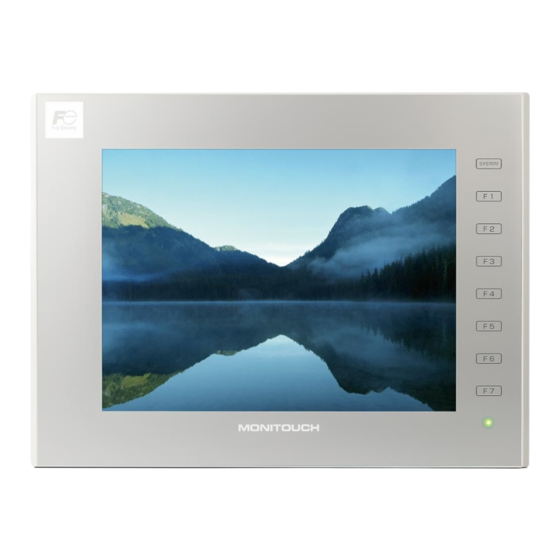
2. Function Switches (Only for Standard/Lite Models) Function Switches (Only for Standard/Lite Models) There are eight function switches provided. [SYSTEM], [F1], [F2], [F3], [F4], [F5], [F6], [F7] * Function switches are not provided on Advanced models. [SYSTEM] Switch The [SYSTEM] switch is an alternate action switch. When it is pressed once, the system menu appears at the top of the screen, and the status bar appears at the bottom right of the screen. -
Page 16: System Menu
3. System Menu System Menu Display Method Advanced Model Press two of the four corners of the V9 series unit screen one by one to display the system menu. 2 cm 2 cm Recognition area Recognition area 2 cm 2 cm 1. -
Page 17: System Menu Types
3. System Menu Standard/Lite Models Press the [SYSTEM] switch. System menu * If the system menu does not appear by pressing the [SYSTEM] switch, the [System Switch Prohibited] checkbox (page 1-6) was selected while editing the screen program on V-SFT version 6. System Menu Types There are two types of system menus as shown below: System menu in RUN mode... - Page 18 3. System Menu Item Description Displayed only when [Use PDF viewer] is selected at [System Setting] [Other] [PDF PDF Viewer Viewer Setting] using V-SFT version 6. This is used to display the PDF viewer. * For details on the PDF viewer, refer to the V9 Series Reference Manual 2. Timing of Displaying the System Menu •...
-
Page 19: Display
3. System Menu Notes • Any switches that are hidden by the system menu are disabled while the system menu is showing. Switches behind the System menu system menu are disabled. • The system menu has priority even over scrolling messages. •... -
Page 20: Security
3. System Menu Security When the [Security] switch is pressed in the system menu, the security level can be changed (by logging in/out) and user names and their passwords for the security function can be registered. * The [Security] switch is displayed only in RUN mode (in operation). When configuring user settings in Local mode, refer to “User Settings”... - Page 21 3. System Menu Logout This section explains the logout procedure for a user at security level 4. 1. Display the system menu , press [Security] in the system menu and press the [Login/Logout] switch. * For details on how to display the system menu, refer to page 1-6. 2.
- Page 22 1-10 3. System Menu User List Users registered for the security function are displayed in list form. In this list, a new user account can be added and the registered user accounts can be deleted or edited. * To display a list of all users in Local mode, refer to “User Settings” (page 2-74). To display the user list by pressing [Security] in the system menu, a user with administrator privileges must log in (administrator authentication).
- Page 23 3. System Menu 1-11 Adding a User Account This section explains how to add a new user account in the user list. A maximum of 32 accounts can be registered on the V9 series unit. 1. Press the [Add] switch in the user list. 2.
- Page 24 1-12 3. System Menu Deleting a User Account This section explains how to delete a registered user account from the user list. 1. Select a user account to delete from the user list and press the [Delete] switch. • Only accounts registered on MONITOUCH can be deleted. Accounts registered in the screen program cannot be deleted.
- Page 25 3. System Menu 1-13 Editing a User Account This section explains how to edit a registered user account in the user list. 1. Select a user account to edit from the user list and press the [Edit] switch. • Only accounts registered on MONITOUCH can be edited. Accounts registered in the screen program cannot be edited.
-
Page 26: Storage Removal
1-14 3. System Menu Storage Removal When the [Storage Removal] switch is pressed in the system menu, the display is changed as shown below. On this screen, access to the connected storage device can be stopped to remove the device safely. - Page 27 3. System Menu 1-15 Removing the Storage Device This section explains how to remove the SD card from the SD card slot. 1. Display the system menu and press the [Storage Removal] switch. * For details on how to display the system menu, refer to page 1-6. 2.
-
Page 28: Storage Viewer
1-16 3. System Menu Storage Viewer When the [Storage Viewer] switch is pressed in the system menu, the display is changed as shown below. This screen is used for checking the information of the connected storage device, or copying, moving, and deleting data between the connected storage devices. The screen is composed of the following items. - Page 29 3. System Menu 1-17 Copy This section explains how to copy data from the SD card inserted in the SD card slot to the USB flash drive connected to the USB-A port. 1. Display the system menu and press the [Storage Viewer] switch. * For details on how to display the system menu, refer to page 1-6.
- Page 30 1-18 3. System Menu Move This section explains how to move data from the SD card inserted in the SD card slot to the USB flash drive connected to the USB-A port. 1. Display the system menu and press the [Storage Viewer] switch. * For details on how to display the system menu, refer to page 1-6.
- Page 31 3. System Menu 1-19 Delete This section explains how to delete data from the SD card inserted in the SD card slot. 1. Display the system menu and press the [Storage Viewer] switch. * For details on how to display the system menu, refer to page 1-6. 2.
-
Page 32: Status Bar
1-20 4. Status Bar Status Bar Display Method Advanced Model Press two of the four corners of the V9 series unit screen one by one to display the status bar. 2 cm 2 cm Recognition area Recognition area 2 cm 2 cm 1. -
Page 33: Status Bar Types
4. Status Bar 1-21 Standard/Lite Models Press the [SYSTEM] switch. Status bar * If the status bar does not appear by pressing the [SYSTEM] switch, [System Switch Prohibited] (page 1-6) or [Status Bar Prohibited] (page 1-22) was selected while editing the screen program on V-SFT version 6. - Page 34 1-22 4. Status Bar Item Description This icon indicates the link status of wireless LAN connection. Wireless LAN status When the V9 series unit is operating in station mode, the signal status is displayed. For details, refer to page 1-27. Indicates the status of communication with the connected device when [Comm.
- Page 35 4. Status Bar 1-23 Notes • Any switches that are hidden by the status bar and detailed status information are disabled while the status bar is showing. Detailed status information Switches behind the status bar and status Status bar information are disabled. •...
-
Page 36: Vpn Connection Status
1-24 4. Status Bar VPN Connection Status This icon is shown when VPN connection is enabled. When VPN connection is disabled, the icon disappears. Connected Disconnected VPN connection disabled When the VPN connection status icon is pressed during connection, the following confirmation dialog appears. -
Page 37: Vnc Connection Status
4. Status Bar 1-25 VNC Connection Status This icon is displayed when the VNC server is used on the V9 series unit with the client connected. When the client is disconnected, the icon disappears. Connected Disconnected When the VNC connection status icon is pressed while the client is connected, the following confirmation dialog appears. -
Page 38: Lan Status / Lan2 Status (Only For Additional Wired Lan I/F Models)
1-26 4. Status Bar LAN Status / LAN2 Status (Only for Additional Wired LAN I/F Models) This icon indicates the link status of LAN/LAN2 connection. Link established Cable disconnected or link not established When the LAN status or LAN2 status icon is pressed, detailed information can be viewed. Detailed information Item Description... -
Page 39: Wireless Lan Status (Only For Wireless Lan I/F Models)
4. Status Bar 1-27 Wireless LAN Status (Only for Wireless LAN I/F Models) This icon indicates the link status of wireless LAN connection. When the V9 series unit is operating in station mode, the signal status is displayed. • When the V9 series is in access point or ad-hoc mode Link established Cable disconnected or link not established •... -
Page 40: Plc 8Way Connection Status
1-28 4. Status Bar PLC 8WAY Connection Status This icon indicates the status of communication with the connected device when [Comm. Error Handling: Disconnect] is selected. Link established Link not established When connected with the simulator *, the following icon is displayed instead. * For details on the simulator, refer to page 2-48. -
Page 41: Chapter 2 Local Mode Screen
Local Mode Screen Switching to Local Mode Local Mode Screen Handling Data Changed in Local Mode... -
Page 42: Switching To Local Mode
1. Switching to Local Mode Switching to Local Mode The procedure for switching from RUN mode to Local mode differs depending on the V9 series model. Advanced Model 1. Press one corner of the screen for at least 2 seconds and release your finger when there is a beep. - Page 43 1. Switching to Local Mode 3. Press the [Local] switch on the displayed system menu. Local mode screen Splash screen Message Progress bar If any of the items given below are placed in a corner on the screen, the system menu will not be displayed. Be sure to press a corner where none of the items are placed.
- Page 44 1. Switching to Local Mode Standard/Lite Models Press the [SYSTEM] switch to display the system menu and then press the [Local] switch Splash screen Progress bar Message Local mode screen If the system menu does not appear by pressing the [SYSTEM] switch, [System Switch Prohibited] is selected (page 1-6).
-
Page 45: Local Mode Screen
2. Local Mode Screen Local Mode Screen The Local mode screen shows various information about the V9 series, such as system information, and screen program information, etc. Also, it works as a system screen for transferring a screen program between a PC and V9 series unit. To transfer a screen program from a PC to the V9 series unit through serial communication, be sure to display this screen. -
Page 46: Composition Of Local Mode Screens
2. Local Mode Screen Composition of Local Mode Screens The Local mode screens are configured as shown below: Local mode screen [RUN] (refer to page 2-6) [System Information] [MONITOUCH Information] (refer to page 2-7.) (refer to page 2-7.) [Screen Data Information] (refer to page 2-8.) [Driver Information] (refer to page 2-8.) [H/W Information] (refer to page 2-9.) [Language Setting]... -
Page 47: Run
2. Local Mode Screen Pressing [RUN] in the menu icons switches to RUN mode. Menu icons Splash screen Message Progress bar RUN screen The splash screen can be changed as desired. For details, refer to the V9 Series Reference Manual 2. -
Page 48: System Information
2. Local Mode Screen System Information Pressing [System Information] in the menu icons brings up the System Information screen. This screen is used to view the information of the V9 series, screen program, etc. This is the screen first displayed when the operation mode is switched from RUN to Local. Menu icons System Information screen 2-1. -
Page 49: Screen Data Information
2. Local Mode Screen 2-2. Screen Data Information The [Screen Data Information] tab window on the System Information screen shows the screen program information. [Screen Data Information] tab window Detailed information Screen displaying device memory Password-protected settings Item Description Display Color Indicates the display color specified in the screen program. -
Page 50: H/W Information
2. Local Mode Screen 2-4. H/W Information The [H/W Information] tab window on the System Information screen shows the hardware information of the V9 series unit. [H/W Information] tab window Item Description H/W revision Indicates the revision number of the hardware. H/W information TSW version Indicates the version of the touch switch firmware. -
Page 51: Language Setting
2-10 2. Local Mode Screen Language Setting Pressing [Language Setting] in the menu icons brings up the Language Setting screen. This screen is used to change the interface language for Local mode and the USB keyboard type. Menu icons Language Setting screen The Language Setting screen can be displayed when any of the following screens are displayed: •... -
Page 52: Keyboard
2. Local Mode Screen 2-11 3-2. Keyboard The [Keyboard] tab window on the Language Setting screen allows you to select the type of the keyboard to connect to the USB-A (master) port. [Keyboard] tab window Select a keyboard type and press the [Apply] switch to confirm the setting. -
Page 53: Lan Setting
2-12 2. Local Mode Screen LAN Setting Pressing [LAN Setting] in the menu icons brings up the LAN Setting screen. This screen is used to set an IP address of the V9 series unit. Menu icons LAN Setting screen When no LAN cable is connected or a link is not established, the indication of the [LAN Setting] icon is changed as follows. -
Page 54: Ip Setting
2. Local Mode Screen 2-13 4-1. IP Setting The [IP Setting] tab window on the LAN Setting screen allows you to set or change the IP address setting of the V9 series unit. [IP Setting] tab window Pressing each setting field Pressing each setting field brings up the system brings up the system... - Page 55 2-14 2. Local Mode Screen IP Address Setting for the V9 Series When using the Ethernet function, set the IP address for the V9 series unit. An IP address can be set either on the V9 unit or in the screen program. Setting on the V9 Unit 1.
- Page 56 2. Local Mode Screen 2-15 Setting Using the V-SFT Editor 1. Select [System Setting] [Ethernet Communication] [Local Port Address] on V-SFT. The [IP Address Setting] window is displayed. 2. Select the [Set IP] checkbox in the [LAN] tab window, and set each item. This is valid when the IP address of the V9 series unit has been Select IP Address from registered in the network table.
- Page 57 2-16 2. Local Mode Screen IP Address This is an address that is used for recognizing each node on the Ethernet and should be unique. The IP address is 32-bit data which consists of the network address and the host address and can be classified into classes A to C depending on the network size.
-
Page 58: Network Table Edit
2. Local Mode Screen 2-17 4-2. Network Table Edit The [Network Table Edit] tab window on the LAN Setting screen allows you to edit and add network tables. [Network Table Edit] tab window After changing the settings, press the [Apply] switch to confirm the settings. - Page 59 2-18 2. Local Mode Screen 4. Press the [Apply] switch to confirm the settings. When the [Select IP Address from Network Table] checkbox is selected and a network table number is specified at [System Setting] [Ethernet Communication] [Local Port Address], any attempt to modify the settings of the specified network table number from the V9 unit will not be reflected to the local port address settings ([IP Setting] tab window).
- Page 60 2. Local Mode Screen 2-19 4. Press the [Apply] switch to confirm the settings. 4-3. Option The [Option] tab window on the LAN Setting screen allows you to set the Ethernet speed and the IP address setting method. [Option] tab window After changing the setting, press the [Apply] switch to confirm the setting.
-
Page 61: Lan2 Setting (Only For Additional Wired Lan I/F Models)
2-20 2. Local Mode Screen LAN2 Setting (Only for Additional Wired LAN I/F Models) Pressing [LAN2 Setting] in the menu icons brings up the LAN2 Setting screen. This screen is used to set an IP address of the additional LAN port of the V9 series unit. Menu icons LAN2 Setting screen Details of the LAN2 Setting screen are the same as “LAN Setting”... - Page 62 2. Local Mode Screen 2-21 IP Address Setting for Additional Wired LAN Setting on the V9 Unit This is the same as “IP Address Setting for the V9 Series” (page 2-14) of “LAN Setting”. Setting Using the V-SFT Editor 1. Select [System Setting] [Ethernet Communication] [Local Port Address] on V-SFT. The [IP Address Setting] window is displayed.
-
Page 63: Network Table Edit
2-22 2. Local Mode Screen 5-2. Network Table Edit This is the same as “Network Table Edit” (page 2-17) of “LAN Setting”. 5-3. Option This is the same as “Option” (page 2-19) of “LAN Setting”. -
Page 64: Wlan Setting (Only For Wireless Lan I/F Models)
2. Local Mode Screen 2-23 WLAN Setting (Only for Wireless LAN I/F Models) Pressing [WLAN Setting] in the menu icons brings up the WLAN Setting screen. This screen is used to configure wireless LAN settings for the V9 series unit. * For details on general specifications and conformance standards for wireless LAN, refer to the V9 Series Hardware Specifications manual. -
Page 65: Ip Setting
2-24 2. Local Mode Screen 6-1. IP Setting The [IP Setting] tab window on the WLAN Setting screen allows you to set or change the IP address setting of the wireless LAN for the V9 series unit. [IP Setting] tab window Pressing each setting Pressing each setting field brings up the system... -
Page 66: Wireless Setting
2. Local Mode Screen 2-25 6-2. Wireless Setting The [Wireless Setting] tab window on the WLAN Setting screen allows you to set the wireless LAN operation mode and authentication method. [Wireless Setting] tab window Item Description Set whether to use (ON status) or not use (OFF status) Status wireless LAN. -
Page 67: Select Ap To Connect
2-26 2. Local Mode Screen The number of characters that can be input depends on the authentication method specified for the wireless LAN. The following characters can be used. • Hexadecimal: 0 to 9, A to F • Text: One-byte alphanumeric characters and symbols (case sensitive) Encryption Authentication Type... - Page 68 2. Local Mode Screen 2-27 Setting the Access Point for Connection 1. Press [WLAN Setting] in the menu icons and open the [Select AP to Connect] tab window. 2. Press the [Search Nearby] switch. Information of nearby access points is displayed in descending order of signal strength. * For details on signal strength, refer to page 1-27.
-
Page 69: Wireless Option
2-28 2. Local Mode Screen 6-4. Wireless Option The [Wireless Option] tab window on the WLAN Setting screen allows you to configure wireless connection settings. • When [Operation Mode] is set to [Access Point] [Wireless Option] tab window Pressing each setting field brings up the system keyboard to be used for configuration. - Page 70 2. Local Mode Screen 2-29 • When [Operation Mode] is set to [Station] [Wireless Option] tab window Pressing each setting field brings up the system keyboard to be used for configuration. Item Description Beacon Receiving Set the interval of beacon transmissions. Interval 15 to 3000 msec (default: 300 msec) KeepAlive Transmission...
-
Page 71: Lan Unit Setting (Only With The Cur-03 Communication I/F Unit Installed)
2-30 2. Local Mode Screen LAN Unit Setting (Only with the CUR-03 Communication I/F Unit Installed) Pressing [LAN Unit Setting] in the menu icons brings up the LAN Unit Setting screen. This screen is used to set the IP address for the CUR-03 communication I/F unit installed on the V9 series unit. -
Page 72: Network Table Edit
2. Local Mode Screen 2-31 2. Select the [Set IP] checkbox in the [Communication Unit] tab window, and set each item. This is valid when the IP address of the V9 series unit has been Select IP Address from registered in the network table. Select a network table number from 0 to Network Table 255 to set the IP address. -
Page 73: Vpn Setting
2-32 2. Local Mode Screen VPN Setting Pressing [VPN Setting] in the menu icons brings up the VPN Setting screen. This screen is used when connecting the V9 series unit to a VPN. Menu icons VPN Setting screen For details on VPN connection, refer to the separately provided “Web Machine Interface” manual. Cloud Setting Pressing [Cloud Setting] in the menu icons brings up the Cloud Setting screen. -
Page 74: E-Mail Setting
2. Local Mode Screen 2-33 E-Mail Setting Pressing [E-Mail Setting] in the menu icons brings up the E-Mail Setting screen. This screen is used to view and configure connection settings and destination settings for sending e-mail notifications. Menu icons E-Mail Setting screen E-Mail Setting screen Press the [Apply] switch to confirm the setting. -
Page 75: Connection Setting
2-34 2. Local Mode Screen 10-1. Connection Setting The [Connection Setting] tab window on the E-Mail Setting screen allows you to configure connection settings for sending e-mail notifications. When e-mail settings have been configured using V-SFT version 6, the settings in the screen program are displayed. -
Page 76: Mail Setting
2. Local Mode Screen 2-35 10-2. Mail Setting The [Mail Setting] tab window on the E-Mail Setting screen allows you to configure destination settings for sending e-mail notifications. When e-mail settings have been configured using V-SFT version 6, the settings in the screen program are displayed. - Page 77 2-36 2. Local Mode Screen 3. Pressing each setting field brings up the system keyboard to be used for configuration. Set the recipient mail address. When [No.] is changed, the set address is copied to the selected number. 4. Press the [OK] switch and then the [Apply] switch. The changed address takes effect. Deleting the Recipient Mail Addresses 1.
-
Page 78: Sram Setting
2. Local Mode Screen 2-37 SRAM Setting Pressing [SRAM Setting] in the menu icons brings up the SRAM Setting screen. This screen is used to format the SRAM area in the V9 series unit. Menu icons SRAM Setting screen If the SRAM area allocated in the V9 series unit is different from the one configured in the [SRAM/Clock Setting] window of V-SFT version 6, the [SRAM Setting] menu icon is changed as shown below. - Page 79 2-38 2. Local Mode Screen Formatting SRAM An SRAM area can be formatted. When the SRAM area is formatted, any saved data (history data saved in SRAM, internal device memory $L, etc.) is completely cleared. Double-check before formatting the SRAM. 1.
-
Page 80: Communication Setting
2. Local Mode Screen 2-39 Communication Setting Pressing [Comm. Setting] in the menu icons brings up the Communication Setting screen. This screen is used to view and configure communication parameters. Menu icons Communication Setting screen Communication Setting screen Indicates the maker, model, and connection port of PLCx. - Page 81 2-40 2. Local Mode Screen Restoring Settings in the Screen Program This section explains how to restore the screen program settings after the communication settings were changed on the V9 series unit. 1. Press [Comm. Setting] in the menu icons. The Communication Setting screen is displayed. 2.
-
Page 82: Communication Parameter
2. Local Mode Screen 2-41 12-1. Communication Parameter The [Communication Setting] tab window on the Communication Setting screen allows you to view and configure parameters for the connected devices. [Communication Parameter] tab window Indicates the maker, model, Changes over the display of and connection port of PLCx. -
Page 83: Connection Target Setting
2-42 2. Local Mode Screen 12-2. Connection Target Setting The [Connection Target Setting] tab window on the Communication Setting screen allows you to view and change the IP address and port number of the connected device. * The [Connection Target Setting] tab window is displayed only when Ethernet connection is used. [Connection Target Setting] tab window Indicates the maker, model, and connection port of PLCx. -
Page 84: Communication I/F Unit Parameters
2. Local Mode Screen 2-43 12-4. Communication I/F Unit Parameters The [Communication I/F Unit Parameters] tab window on the Communication Setting screen allows you to view and change settings regarding communication I/F units. (Not all communication I/F units allow setting changes.) * The [Communication I/F Unit Parameters] tab is displayed only when a communication I/F unit is specified for connection. -
Page 85: Multi-Link2
2-44 2. Local Mode Screen 12-6. Multi-Link2 The [Multi-Link2] tab window on the Communication Setting screen allows you to view and configure multi-link2, multi-link2 (Ethernet), and 1 : n multi-link2 (Ethernet) settings. * The [Multi-Link2] tab window is available only when the connection mode is multi-link2, multi-link2 (Ethernet), or 1 : n multi-link2 (Ethernet). - Page 86 2. Local Mode Screen 2-45 • For a slave station [Multi-Link2] tab window Indicates the maker, model, and connection port of Changes over the display of PLCx. the communication settings between PLC1 to PLC8. Pressing each setting field brings up the system keyboard to be used for configuration.
- Page 87 2-46 2. Local Mode Screen • For a slave station [Multi-Link2] tab window Indicates the maker, model, and connection port of Changes over the display of PLCx. the communication settings between PLC1 to PLC8. Pressing each setting field brings up the system keyboard to be used for configuration.
- Page 88 2. Local Mode Screen 2-47 • For a slave station [Multi-Link2] tab window Indicates the maker, model, and connection port of Changes over the display of PLCx. the communication settings between PLC1 to PLC8. Pressing each setting field brings up the system keyboard to be used for configuration.
-
Page 89: Simulator Setting
2-48 2. Local Mode Screen Simulator Setting Pressing [Simulator Setting] in the menu icons brings up the Simulator Setting screen. This screen is used to show the information of the simulator to use, and select whether or not to use the simulator. -
Page 90: System Setting
2. Local Mode Screen 2-49 System Setting Pressing [System Setting] in the menu icons brings up the System Setting screen. This screen is used to change the settings for the buzzer and backlight. Menu icons System Setting screen System Setting screen Press the [Apply] switch to confirm the setting. -
Page 91: Buzzer Setting
2-50 2. Local Mode Screen 14-1. Buzzer Setting The [Buzzer Setting] tab window on the System Setting screen is used to change the buzzer sound. [Buzzer Setting] tab window After changing the setting, press the [Apply] switch to confirm the setting. Item Description Standard... -
Page 92: Date/Time Setting
2. Local Mode Screen 2-51 Date/Time Setting Pressing [Date/Time Setting] in the menu icons brings up the Date/Time Setting screen. This screen is used to correct the date and time of the built-in clock in the V9 series unit. Set whether to use the built-in clock in the V9 series unit or the clock in the PLC by selecting [System Setting] ... - Page 93 2-52 2. Local Mode Screen • When changing the year: Press the year portion on the calendar and select a year to set using the [] and [] switches. When a position other than the [] and [] switches is pressed, the calendar is changed to the set year.
- Page 94 2. Local Mode Screen 2-53 Time Setting 1. Press [Date/Time Setting] in the menu icons. The Date/Time Setting screen is displayed. 2. Press the time setting field. The system keyboard appears. Input a time to set. 3. Press the [Set] switch to confirm the setting. The clock displayed on the top right is modified.
-
Page 95: Storage Transfer
2-54 2. Local Mode Screen Storage Transfer Pressing [Storage Transfer] in the menu icons brings up the Storage Transfer screen. This screen is used for transferring data such as screen programs between the V9 series unit and the storage device. Menu icons Storage Transfer screen Storage Transfer screen... -
Page 96: Storage Folder Configuration
2. Local Mode Screen 2-55 16-1. Storage Folder Configuration The table below lists folder names, contents, and file names. For details, refer to the V9 Series Reference Manual 2. Storage (SD card/USB flash drive) EXT0000 (access folder name: user-definable within 64 one-byte uppercase alphanumeric characters) Folder Name Contents File Name... - Page 97 2-56 2. Local Mode Screen Folder Name Contents File Name Transfer Direction (fixed) Windows font file V9 Storage SCRN WFM0000.BIN - WFM4095.BIN (messages) Snapshot images of a V9 Storage SNAP VD00000.JPG - VD32767.JPG network camera V9 Storage SRAM SRAM backup data SRM0000.BIN...
-
Page 98: Transferring A Screen Program
2. Local Mode Screen 2-57 16-2. Transferring a Screen Program This section explains how to transfer data with an SD card inserted into the SD card slot on the V9 series unit. 1. SD card insertion Insert an SD card into the SD card slot on the back of the MONITOUCH. Enlarged view SD card orientation Rear... - Page 99 2-58 2. Local Mode Screen When [Display Storage] Is Selected: 1. When [Display Storage] is selected, the following screen appears. Information of the folder currently selected Free space in the SD card Folder name currently selected Used for checking or changing folder names.
- Page 100 2. Local Mode Screen 2-59 4. Transfer data selection After selecting the folder under [Select Data], select the data to transfer. The following table shows the details of data to transfer. Data to Transfer Description Screen Data Screen program file used on MONITOUCH System program file for MONITOUCH Font Data Transfer when updating of the system program is required.
- Page 101 2-60 2. Local Mode Screen When [Display Storage] Is Selected: 1. When [Display Storage] is selected, the following screen appears. Information of the folder currently selected Free space in the SD card Folder name currently selected Starts transfer from MONITOUCH to the storage device.
- Page 102 2. Local Mode Screen 2-61 When [Display Storage] Is Selected: 1. When [Display Storage] is selected, the following screen appears. The screen program in MONITOUCH is compared with the screen program (in the DSP folder) in the access folder. Information of the folder currently selected Free space in the SD card...
-
Page 103: Saving Backup Copies Of Sram
2-62 2. Local Mode Screen 16-3. Saving Backup Copies of SRAM This section explains how to save backup copies in an SD card inserted into the SD card slot on the V9 series unit. 1. SD card insertion Insert an SD card into the SD card slot on the back of the MONITOUCH. For details, refer to page 2-57. - Page 104 2. Local Mode Screen 2-63 6. Data transfer or comparison start Check the storage information and press the [Start] switch. During data transfer or comparison, the [Start] switch changes to [Transferring] and the [Transferring data ... (Storage)] dialog is displayed. Data transfer or comparison start During data transfer or comparison 7.
-
Page 105: Deleting Data From Storage
2-64 2. Local Mode Screen 16-4. Deleting Data from Storage This section explains how to delete data from an SD card inserted into the SD card slot on the V9 series unit. 1. SD card insertion Insert an SD card into the SD card slot on the back of the MONITOUCH. For details, refer to page 2-57. -
Page 106: Message Dialog Displayed During Data Transfer (Between V9 And Storage)
2. Local Mode Screen 2-65 16-5. Message Dialog Displayed during Data Transfer (between V9 and Storage) If an error occurs during data transfer, the message dialog shown on the right is displayed on the V9 series unit. Messages and their contents are shown below. Messages Description Work normally finished. -
Page 107: I/O Check
2-66 2. Local Mode Screen I/O Check Pressing [I/O Check] in the menu icons brings up the I/O Check screen. This screen is used to check the touch switch and function switch operations as well as the connection status of the external devices (USB mouse, storage device, etc.) connected to the V9 series unit. A network test can be performed by pinging a specified IP address from the V9 series unit. -
Page 108: Touch Switch
2. Local Mode Screen 2-67 17-1. Touch Switch The [Touch switches and media] tab window on the I/O Check screen allows you to check the touch switch operation as well as the connection status of an external device. [Touch switches and media] tab window Moves to the touch switch test screen (page 2-68). - Page 109 2-68 2. Local Mode Screen Touch Switch Test If a touch switch does not activate at all, or if an operation is performed without pressing any touch switch, check if the touch switches on the V9 panel are working properly. 1.
- Page 110 2. Local Mode Screen 2-69 Touch Switch Adjustment If a position different from the pressed position turned white on the touch switch test described previously, follow the steps described below to adjust the touch switch position. * Touch switch adjustment is not available on Advanced models. 1.
-
Page 111: Network Test
2-70 2. Local Mode Screen USB-A/Storage Test This section describes how to check the connection status of the storage device or other devices connected to the USB-A port. Checking the Connection Status If [Disconnected] is displayed on the screen, the storage device or USB device is not connected or identified correctly. - Page 112 2. Local Mode Screen 2-71 Network Test This section describes how to check the network status by checking the connection with a specified IP address from the V9 series unit. 1. Press [I/O Check] in the menu icons and open the [Network Test] tab window. 2.
-
Page 113: Duplicate Ip Test
2-72 2. Local Mode Screen 17-3. Duplicate IP Test The [Duplicate IP Test] tab window on the I/O Check screen allows you to check if there are any duplicate IP addresses between the V9 series unit and the devices on the network. [Duplicate IP Test] tab window Duplicate IP Test 1. -
Page 114: Rgb Adjustment
2. Local Mode Screen 2-73 17-4. RGB Adjustment The [RGB Adjustment] tab window on the I/O Check screen allows you to perform adjustments for the RGB input screen. * The [RGB Adjustment] tab is displayed only when the optional “GUR-01”, “GUR-10”, or “GUR-11” unit is installed. -
Page 115: User Settings
2-74 2. Local Mode Screen User Settings Pressing [User Settings] in the menu icons brings up the User Settings screen. This screen is used to register and view users who can use password-protected functions. User accounts can be added, deleted, and edited on this screen. The following functions require user settings. - Page 116 2. Local Mode Screen 2-75 Administrator Authentication Authentication of administrator privileges is required before adding a new user account or deleting/editing a registered user account, if any. Without administrator privileges, no account can be added, deleted, nor edited. Addition, deletion and editing of a user account possible Addition, deletion and editing of a user account impossible...
- Page 117 2-76 2. Local Mode Screen Adding a User Account This section explains how to add a new user account in the administrator mode. A maximum of 32 user accounts can be registered on the V9 series unit. 1. Press the [Add] switch. Enter a user name and password to add.
- Page 118 2. Local Mode Screen 2-77 Deleting a User Account This section explains how to delete a registered user account in the administrator mode. 1. Select a user account to delete from the user list and press the [Delete] switch. • User accounts that can be deleted - The account of an administrator user that is currently logged in - User accounts which were registered on MONITOUCH ([Registered in: Main unit]) and are not granted administrator privileges...
- Page 119 2-78 2. Local Mode Screen Editing a User Account This section explains how to edit a registered user account in the administrator mode. 1. Select a user account to edit from the user list and press the [Edit] switch. • User accounts that can be edited - The account of an administrator user that is currently logged in - User accounts which were registered on MONITOUCH ([Registered in: Main unit]) and are not granted administrator privileges...
-
Page 120: Standards (Only For Wireless Lan I/F Models)
2. Local Mode Screen 2-79 Standards (Only for Wireless LAN I/F Models) Pressing [Standards] in the menu icons brings up the Standards screen. This screen is for viewing certification information of wireless LAN for the V9 series. Menu icons Standards screen Standards and Certifications Certification on Wireless LAN FCC / IC Caution... -
Page 121: Os Update
2-80 2. Local Mode Screen OS Update Pressing [OS Update] in the menu icons brings up the OS Update screen. This screen is used when manually updating the operating system (OS) for operating the V9 series unit. * The [OS Update] menu icon is displayed only when a storage device (SD card or USB flash drive) containing the file for updating the operating system is connected. -
Page 122: Handling Data Changed In Local Mode
3. Handling Data Changed in Local Mode 2-81 Handling Data Changed in Local Mode The following items set in the screen program can be changed on the V9 series unit. Item Setting in V-SFT Version 6 Setting in Local Mode [LAN Setting] (page 2-12) [System Setting] ... - Page 123 2-82 3. Handling Data Changed in Local Mode 5) Start downloading to MONITOUCH Click [PC ]. Screen program transfer starts. When the following dialog is displayed, click [Yes]. * The language setting (page 2-10) of the V9 series unit will be set to English if the INI file is deleted.
- Page 124 3. Handling Data Changed in Local Mode 2-83 Prohibition of Setting Change in Local Mode Some settings that can be configured in Local mode can be prohibited from being changed on the V9 series unit. Setting in V-SFT Version 6 Select [System Setting] ...
- Page 125 2-84 3. Handling Data Changed in Local Mode V9 Series Local Mode When the Local-mode prohibition setting has been made in V-SFT version 6, the menu icon displayed in Local mode on the V9 series unit is changed as follows: Example: [LAN Setting] menu icon Without prohibition setting With prohibition setting...
- Page 126 3. Handling Data Changed in Local Mode 2-85 2. Press the [Apply] switch. The following confirmation dialog appears. Press the [OK] switch. 3. All items that were prohibited in Local mode become unprotected. 4. To validate the Local-mode prohibition setting again, open the [System Information] [Screen Data Information] tab window, and press the [Relock] switch.
- Page 127 2-86 3. Handling Data Changed in Local Mode Please use this page freely.
-
Page 128: Error Handling
Error Handling Error Messages Troubleshooting... -
Page 129: Error Messages
1. Error Messages Error Messages There are three kinds of error messages displayed on the V9 series: 1. Setup error 2. Screen program error 3. Communication error Setup Error When no screen program is present or no system program has been transferred, the following message is displayed on the V9 series unit. -
Page 130: Error Numbers
1. Error Messages 2-1. Error Numbers Check the contents of the error (= error number) according to the item name and sub-item number, and remove the error. Sub-item number (Refer to page 3-8.) Item name (Refer to page 3-8.) Error number * Error numbers with “*”... - Page 131 1. Error Messages Error No. Contents Solution The memory capacity is insufficient. Reduce the number set for [Number of Data to Save] under [Internal Storage Setting] or [Number of Monitoring Alarms] in the [Alarm Server] window. Delete the following settings if not necessary. •...
- Page 132 1. Error Messages Error No. Contents Solution Switch operating area error Reset the switch operating area. Statistic graph % display No. exceeding Contact your local distributor. Multi data exceeding The ordinal number for data block selection (a Check the ordinal number for data block maximum of four) is duplicated.
- Page 133 1. Error Messages Error No. Contents Solution Multi-language initial display string No. error Contact your local distributor. Multi-language selection string number error MR400 format table setting: String code error There is an invalid code after “\” in the string. MR400 format table setting: String size error The total size of the string is too large.
- Page 134 1. Error Messages Error No. Contents Solution I/F driver not registered Transfer the I/F driver. Or check the device memory of the item. The device memory map number is not set in Check the device memory map settings, and set the [Logging Server] window.
- Page 135 1. Error Messages Error No. Contents Solution The function set for the serial port is duplicated. Error : 166 (Header : x) Sub-item number The sub-item number denotes the ports as shown below: 0: CN1 1: MJ1 2: MJ2 Specify a unique function (simulator, etc.) for each port.
- Page 136 1. Error Messages Error No. Contents Solution An alarm type is not specified for the alarm Check the alarm type setting of monitored server. alarms for the relevant alarm block number at [System Setting] [Alarm Server]. Item Name The item name indicates the screen or other locations where the error was detected. Sub-item Number The sub-item number indicates the number of the screen where the error was detected.
-
Page 137: Communication Error
1. Error Messages Communication Error When communication is not established between a V9 series unit and a controller, or any abnormality (noise etc.) is detected, the communication error screen is displayed on the V9 series unit. The display of an error differs depending on the option selected for [Comm. Error Handling]. * The setting for [Comm. - Page 138 3-10 1. Error Messages • When [Comm. Error handling: Disconnect] is selected: The status bar appears without displaying any error messages, and indicates the icon for “link not established” for PLC 8WAY connection (page 1-28). When a time-out error is detected, communication is discontinued and the next communication is attempted.
- Page 139 1. Error Messages 3-11 3-1. Error Messages Error Messages Contents Solution 1. Check the settings in the [Hardware Setting] [PLC Properties] window. Although a request to send is given to a Check that the cable is correctly connected. Time-Out controller, no answer is returned within the specified time.
-
Page 140: Error Messages
3-12 1. Error Messages Ethernet-specific Errors Error Messages Description Solution $s518* The UDP socket port cannot be Check that the setting on the target station is Send Error allocated. consistent with the network table setting. Turn the power off and back on again, or The TCP socket cannot be Failed to create a TCP socket. -
Page 141: Troubleshooting
2. Troubleshooting 3-13 Troubleshooting In the Event of an Error Perform the steps below: 1. If the current error matches a symptom in the following table, correct it by following the instructions provided. 2. If the error does not match the symptoms in the table, contact your local distributor (specified on the back cover). - Page 142 3-14 2. Troubleshooting Symptoms Causes Solutions Communications have been Noise may cause the error. Check if appropriate measures are taken successful. However, against noise. “Communication Error: Parity” or “Communication Error: Framing” Example: suddenly occurs. • Check if communication cables are bundled together with power cables.
- Page 143 2. Troubleshooting 3-15 Symptoms Causes Solutions Switches do not work. 1) Switches do not work in RUN mode. A 1) Check the settings of switch functions, beep sounds. etc. on V-SFT version 6. The switch interlock is enabled. Switch settings are incorrect.
- Page 144 3-16 2. Troubleshooting Symptoms Causes Solutions The system menu cannot be • For Advanced models • For Advanced models displayed in RUN mode. Any of the following parts are placed in Be sure to press a corner where none of the corners of the screen.
- Page 145 www.monitouch.com 890-1, Kamikashiwano-machi, Hakusan-shi, Ishikawa, Sales 924-0035 Japan TEL +81-76-274-2144 FAX +81-76-274-5136 1068NE2 80800000...
Need help?
Do you have a question about the Monitouch V9 Series and is the answer not in the manual?
Questions and answers