Table of Contents
Advertisement
Quick Links
Advertisement
Table of Contents

Related Manuals for Libelium Waspmote Plug & Sense! Smart Agriculture 3.0

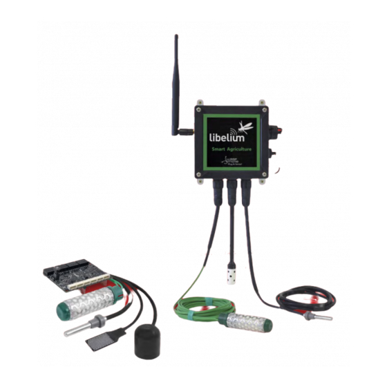
Summary of Contents for Libelium Waspmote Plug & Sense! Smart Agriculture 3.0
- Page 1 Smart Agriculture 3.0 Smart Agriculture 3.0 Technical Guide Technical Guide...
-
Page 2: Table Of Contents
Index Document version: v7.8 - 02/2020 © Libelium Comunicaciones Distribuidas S.L. INDEX 1. General ..............................5 1.1. General and safety information ..............................5 1.2. Conditions of use ..................................5 2. New version: Smart Agriculture v3.0 ....................7 3. Waspmote Plug & Sense! ........................8 3.1. - Page 3 Index 5.3.3. Socket .....................................34 5.4. Soil temperature sensor (DS18B20) ............................ 36 5.4.1. Specifications ................................36 5.4.2. Measurement Process...............................36 5.4.3. Socket .....................................36 5.5. Soil temperature sensor (Pt-1000) ............................. 37 5.5.1. Specifications ................................37 5.5.2. Measurement process ..............................37 5.5.3. Socket .....................................38 5.6. Trunk diameter dendrometer (Ecomatik DC3) ....................... 39 5.6.1.
- Page 4 Index 6. Board configuration and programming ..................69 6.1. Hardware configuration ................................. 69 6.2. API ........................................69 6.2.1. Agriculture Class .................................69 6.2.2. dendrometerClass ..............................70 6.2.3. ds18b20Class ................................70 6.2.4. leafWetnessClass ................................70 6.2.5. pt1000Class ..................................70 6.2.6. radiationClass ................................70 6.2.7. watermarkClass ................................71 6.2.8. weatherStationClass..............................71 7.
-
Page 5: General
All documents and any examples they contain are provided as-is and are subject to change without notice. Except to the extent prohibited by law, Libelium makes no express or implied representation or warranty of any kind with regard to the documents, and specifically disclaims the implied warranties and conditions of merchantability and fitness for a particular purpose. - Page 6 General Further information you may need can be found at: http://www.libelium.com/development/waspmote The “General Conditions of Libelium Sale and Use” document can be found at: http://www.libelium.com/development/waspmote/technical_service v7.8...
-
Page 7: New Version: Smart Agriculture V3.0
Development website. You can get more information about the generation change on the document “New generation of Libelium product lines”. Differences of Smart Agriculture v3.0 with previous versions: Included the new BME280 temperature, humidity and air pressure sensor. This tiny, digital and cost-efficient •... -
Page 8: Waspmote Plug & Sense
It has been specially designed to be scalable, easy to deploy and maintain. Note: For a complete reference guide download the “Waspmote Plug & Sense! Technical Guide” in the Development of the section Libelium website. 3.1. Features Robust waterproof IP65 enclosure •... -
Page 9: General View
Waspmote Plug & Sense! 3.2. General view This section shows main parts of Waspmote Plug & Sense! and a brief description of each one. In later sections all parts will be described deeply. 3.2.1. Specifications Material: polycarbonate • Sealing: polyurethane •... - Page 10 Waspmote Plug & Sense! Figure: Control side of the enclosure Control side of the enclosure for 4G model Figure: Sensor side of the enclosure -10- v7.8...
- Page 11 Waspmote Plug & Sense! Figure: Antenna side of the enclosure Figure: Front view of the enclosure Figure: Back view of the enclosure -11- v7.8...
-
Page 12: Parts Included
Waspmote Plug & Sense! Figure: Warranty stickers of the enclosure Important note: Do not handle black stickers seals of the enclosure (Warranty stickers). Their integrity is the proof that Waspmote Plug & Sense! has not been opened. If they have been handled, damaged or broken, the warranty is automatically void. -
Page 13: Identification
Waspmote Plug & Sense! 3.2.3. Identification Each Waspmote model is identified by stickers. Next figure shows front sticker. Model identification colour Enclosure model Figure: Front sticker of the enclosure There are many configurations of Waspmote Plug & Sense! line, all of them identified by one unique sticker. Next image shows all possibilities. - Page 14 Waspmote Plug & Sense! Moreover, Waspmote Plug & Sense! includes a back sticker where it is shown identification numbers, radio MAC addresses, etc. It is highly recommended to annotate this information and save it for future maintenance. Next figure shows it in detail. Figure: Back sticker Sensor probes are identified too by a sticker showing the measured parameter and the sensor manufacturer reference.
-
Page 15: Sensor Probes
Waspmote Plug & Sense! 3.3. Sensor probes Sensor probes can be easily attached by just screwing them into the bottom sockets. This allows you to add new sensing capabilities to existing networks just in minutes. In the same way, sensor probes may be easily replaced in order to ensure the lowest maintenance cost of the sensor network. -
Page 16: Solar Powered
Waspmote Plug & Sense! 3.4. Solar powered The battery can be recharged using the waterproof USB cable but also the external solar panel option. The external solar panel is mounted on a 45º holder which ensures the maximum performance of each outdoor installation. -
Page 17: External Battery Module
Waspmote Plug & Sense! 3.5. External Battery Module The External Battery Module (EBM) is an accessory to extend the battery life of Plug & Sense!. The extension period may be from months to years depending on the sleep cycle and radio activity. The daily charging period is selectable among 5, 15 and 30 minutes with a selector switch and it can be combined with a solar panel to extend even more the node’s battery lifetime. -
Page 18: Programming The Nodes
Waspmote Plug & Sense! 3.6. Programming the Nodes Waspmote Plug & Sense! can be reprogrammed in two ways: The basic programming is done from the USB port. Just connect the USB to the specific external socket and then to the computer to upload the new firmware. Figure: Programming a node Over the Air Programming (OTAP) is also possible once the node has been installed (via WiFi or 4G radios). -
Page 19: Program In Minutes
Plug & Sense!. Advanced programming options are available, depending on the license selected. Check how easy it is to handle the Programming Cloud Service at: https://cloud.libelium.com/ Figure: Programming Cloud Service -19-... -
Page 20: Radio Interfaces
Waspmote Plug & Sense! 3.8. Radio interfaces Frequency Transmission Certification Radio Protocol Sensitivity Range* bands power XBee-PRO 802.15.4 802.15.4 2.4 GHz 10 dBm -100 dBm 750 m FCC, IC, ANATEL, XBee-PRO 802.15.4 802.15.4 2.4 GHz 18 dBm -100 dBm 1600 m XBee 868LP 868 MHz 14 dBm... -
Page 21: Industrial Protocols
Waspmote Plug & Sense! 3.9. Industrial Protocols Besides the main radio of Waspmote Plug & Sense!, it is possible to have an Industrial Protocol module as a secondary communication option. This is offered as an accessory feature. The available Industrial Protocols are RS-485, Modbus (software layer over RS-485) and CAN Bus. This optional feature is accessible through an additional, dedicated socket on the antenna side of the enclosure. - Page 22 Waspmote Plug & Sense! Finally, the user can choose between 2 probes to connect the desired Industrial Protocol: A standard DB9 connector and a waterproof terminal block junction box. These options make the connections on industrial environments or outdoor applications easier. Figure: DB9 probe Figure: Terminal box probe -22-...
-
Page 23: Gps
Waspmote Plug & Sense! 3.10. GPS Any Plug & Sense! node can incorporate a GPS receiver in order to implement real-time asset tracking applications. The user can also take advantage of this accessory to geolocate data on a map. An external, waterproof antenna is provided;... -
Page 24: Models
Waspmote Plug & Sense! 3.11. Models There are some defined configurations of Waspmote Plug & Sense! depending on which sensors are going to be used. Waspmote Plug & Sense! configurations allow to connect up to six sensor probes at the same time. Each model takes a different conditioning circuit to enable the sensor integration. - Page 25 The main applications for this Waspmote Plug & Sense! model are precision agriculture, irrigation systems, greenhouses, weather stations, etc. Refer to for more information. Libelium website Figure: Smart Agriculture PRO Waspmote Plug & Sense! model -25- v7.8...
- Page 26 Ultrasound (distance measurement) 9246-P Figure: Sensor sockets configuration for Smart Agriculture PRO model * Ask Libelium for more information. Sales Department Note: For more technical information about each sensor probe go to the Development section on the Libelium website. -26- v7.8...
-
Page 27: Hardware
Hardware 4. Hardware 4.1. General description The Waspmote Agriculture v3.0 Board allows to monitor multiple environmental parameters involving a wide range of applications, from growing development analysis to weather observation. For this, it has been provided with sensors for air and soil temperature and humidity, luminosity, solar radiation (PAR and UV), wind speed and direction, rainfall, atmospheric pressure, leaf wetness, distance and fruit or trunk diameter (dendrometer). -
Page 28: Agriculture V3.0 Board Versions
Hardware 4.4. Agriculture v3.0 Board versions Note: Since April 2019, Libelium only distributes Smart Agriculture in the PRO version, which supports all sensors in this family. The normal version was discontinued. Some notes about Smart Agriculture normal remain for the former customers. -
Page 29: Sensors
Sensors 5. Sensors 5.1. Temperature, humidity and pressure sensor (BME280) Note: Only one BME280 sensor is supported at the same time. 5.1.1. Specifications Electrical characteristics Supply voltage: 3.3 V • Sleep current typical: 0.1 μA • Sleep current maximum: 0.3 μA •... -
Page 30: Measurement Process
• float temp; Agriculture.ON(); // Reads the temperature from BME280 sensor temp = Agriculture.getTemperature(); Humidity: Reading code: • float humd; Agriculture.ON(); // Reads the humidity from BME280 sensor humd = Agriculture.getHumidity(); Pressure: Reading code: • float pres; Agriculture.ON(); // Reads the pressure from BME280 sensor pres = Agriculture.getPressure(); You can find a complete example code for reading the BME280 sensor in the following link: http://www.libelium.com/development/waspmote/examples/ag-v30-01-temperature-sensor-reading -30- v7.8... -
Page 31: Socket
Sensors 5.1.3. Socket Figure: Image of the socket for the BME280 sensor In the image above we can see highlighted the four pins of the terminal block where the sensor must be connected to the board. The white dot on the BME280 must match the mark on the Agriculture sensor board. -31- v7.8... -
Page 32: Leaf Wetness Sensor (Lws)
// Read the leaf wetness sensor value_lw = lwSensor.getLeafWetness(); You can find a complete example code for reading the leaf wetness sensor in the following link: http://www.libelium.com/development/waspmote/examples/ag-v30-02-leaf-wetness-sensor-reading 5.2.3. Socket Figure: Image of the socket for the Leaf Wetness sensor In the image above we can see highlighted the two pins of the terminal block where the sensor must be connected to the board. -
Page 33: Soil Moisture Sensor (Watermark)
Sensors 5.3. Soil moisture sensor (Watermark) 5.3.1. Specifications Measurement range: 0 ~ 200 cb Frequency Range: 50 ~ 10000 Hz approximately Diameter: 22 mm Length: 76 mm Terminals: AWG 20 Figure: Watermark sensor Figure: Output frequency of the Watermark sensor circuit with respect to the resistance of the sensor 5.3.2. -
Page 34: Socket
// Print the watermark measures USB.print(F(“Watermark 1 - Frequency: “)); USB.print(watermark1); USB.println(F(“ Hz”)); USB.print(F(“Watermark 2 - Frequency: “)); USB.print(watermark2); USB.println(F(“ Hz”)); USB.print(F(“Watermark 3 - Frequency: “)); USB.print(watermark3); USB.println(F(“ Hz”)); You can find a complete example code for reading the Watermark sensors in the following link: http://www.libelium.com/development/waspmote/examples/ag-v30-07-watermark-sensor-reading 5.3.3. Socket Figure: Image of the socket for the Watermark sensor -34- v7.8... - Page 35 Sensors Three sockets for Watermark sensors have been placed in the agriculture board (marked in the image in the figure above) and the electronics necessary for powering and signal conditioning, so that the soil moisture can be measured at three different depths. Figure: Illustration of the three Watermark sensors placed at different depths -35- v7.8...
-
Page 36: Soil Temperature Sensor (Ds18B20)
// Read the temperature sensor temp = ds18b20.readDS18b20(); You can find a complete example code for reading the DS18B20 sensor in the following link: http://www.libelium.com/development/waspmote/examples/ag-v30-12-ds18b20-temperature-sensor-reading 5.4.3. Socket Figure: Image of the socket for the DS18B20 sensor The sensor must be connected to its adaptation stage through a 2.54 mm pitch. We can see an image with the 3 pins of this socket corresponding to the sensor in the previous figure. -
Page 37: Soil Temperature Sensor (Pt-1000)
This sensor can only be read by Smart Agriculture PRO version. Reading code: // Variable to store the read value float value_PT1000; // Instance object pt1000Class pt1000Sensor; Agriculture.ON(); // Read PT1000 sensor value_PT1000 = pt1000Sensor.readPT1000(); You can find a complete example code for reading the Pt-1000 sensor in the following link: http://www.libelium.com/development/waspmote/examples/ag-v30-06-pt1000-sensor-reading -37- v7.8... -
Page 38: Socket
Sensors 5.5.3. Socket Figure: Image of the socket for the Pt-1000 sensor The sensor must be connected to its adaptation stage through a 2.54 mm pitch. We can see an image with the two pins of this socket corresponding to the sensor in the previous figure. Both pins of the sensor can be connected to any of the two ways, since there is no polarity to be respected. -
Page 39: Trunk Diameter Dendrometer (Ecomatik Dc3)
Sensors 5.6. Trunk diameter dendrometer (Ecomatik DC3) 5.6.1. Specifications Operation temperature: -30 ~ 40 ºC Operation humidity: 0 ~ 100% RH Trunk/branch diameter: from 5 cm Accuracy: ±3.3 μm Temperature coefficient: <1,4μm/K Linearity: 0.7% Output range: 0 ~ 20 kΩ Range of the sensor: function of the size of the tree: Tree Diameter (cm) Measuring range in diameter (mm) -
Page 40: Installation Process
This sensor can only be read by Smart Agriculture PRO version. Reading code: // Variable to store the read value float value_dendrometer; // Instance object dendrometerClass dendSensor r(SENS_SA_DC3); Agriculture.ON(); // Read the dendrometer sensor value_dendrometer = dendSensor.readDendrometer(); You can find a complete example code for reading the dendrometer sensor in the following link: http://www.libelium.com/development/waspmote/examples/ag-v30-05-dendrometer-sensor-reading -40- v7.8... -
Page 41: Socket
// the difference between this value and reference value_dendrometer = dendSensor.readGrowth(); You can find a complete example code for reading the dendrometer sensor in the following link: http://www.libelium.com/development/waspmote/examples/ag-v30-05b-dendrometer-sensor-reading-with-reference 5.6.4. Socket Figure: Image of the socket for the dendrometers Any of the three dendrometers available may be connected to Waspmote through the two 2.54 mm pitch terminal blocks marked in the image in the figure above. -
Page 42: Stem Diameter Dendrometer (Ecomatik Dd-S)
Sensors 5.7. Stem diameter dendrometer (Ecomatik DD-S) 5.7.1. Specifications Stem/branch diameter: 0 ~ 5 cm Range of the sensor: 5.5 mm Output range: 0 ~ 20 kΩ Accuracy: ±2 μm Temperature coefficient: <0.1μm/K Operation temperature: -30 ~ 40 ºC Operation humidity: 0 ~ 100% RH Cable length: 2 m Figure: Ecomatik DD-S sensor Figure: Ecomatik DF sensor... -
Page 43: Measurement Process
You can find a complete example code for reading the dendrometer sensor in the following link: http://www.libelium.com/development/waspmote/examples/ag-v30-05-dendrometer-sensor-reading There is another possibility to take measures using the dendrometer. First, a reference is stored at the beginning of the code with the function (it should be run inside the setup()). -
Page 44: Socket
// the difference between this value and reference value_dendrometer = dendSensor.readGrowth(); You can find a complete example code for reading the dendrometer sensor in the following link: http://www.libelium.com/development/waspmote/examples/ag-v30-05b-dendrometer-sensor-reading-with-reference 5.7.4. Socket Figure: Image of the socket for the dendrometers Any of the three dendrometers available may be connected to Waspmote through the two 2.54mm pitch terminal blocks marked in the image in the figure above. -
Page 45: Fruit Diameter Dendrometer (Ecomatik Df)
Sensors 5.8. Fruit diameter dendrometer (Ecomatik DF) 5.8.1. Specifications Fruit diameter: 0 ~ 11 cm Range of the sensor: 7.5 mm Output range: 0 ~ 20 kΩ Accuracy: ±2 μm Temperature coefficient: <0.1 μm/K Operation temperature: -30 ~ 40 ºC Operation humidity: 0 ~ 100% RH Cable length: 2 m Figure: Ecomatik DF sensor... -
Page 46: Installation Process
Sensors 5.8.2. Installation process Detach the front frame of the dendrometer to allow you fix the fruit to be measured. Insert the fruit carefully between the fixing wires until it rests onto the hind plate. Curve the fixing wires accordingly so as to fit the shape of the fruit. -
Page 47: Measurement Process
“Board configuration and programming”). This sensor can only be read by Smart Agriculture PRO version. Reading code: // Variable to store the read value float value_dendrometer; // Instance object dendrometerClass dendSensor(SENS_SA_DF); Agriculture.ON(); // Read the dendrometer sensor value_dendrometer = dendSensor.readDendrometer(); You can find a complete example code for reading the dendrometer sensor in the following link: http://www.libelium.com/development/waspmote/examples/ag-v30-05-dendrometer-sensor-reading -47- v7.8... - Page 48 // Variable to store the read value float value_dendrometer; // Instance object dendrometerClass dendSensor(SENS_SA_DC3); Agriculture.ON(); // This function reads the dendrometer value // and sets it as zero millimeters reference dendSensor.setReference(); // Read the dendrometer sensor and return the // the difference between this value and reference value_dendrometer = dendSensor.readGrowth(); You can find a complete example code for reading the dendrometer sensor in the following link: http://www.libelium.com/development/waspmote/examples/ag-v30-05b-dendrometer-sensor-reading-with-reference -48- v7.8...
-
Page 49: Socket
Sensors 5.8.4. Socket Figure: Image of the socket for the dendrometers Any of the three dendrometers available may be connected to Waspmote through the 2.54 mm pitch terminal blocks marked in the image in the figure above. The pins corresponding to the sensor in this terminal block (highlighted in the figure) provide the sensor with connection to ground, power supply and to the analog-to-digital converter differential input. -
Page 50: Solar Radiation Sensor - Par (Sq-110)
Sensors 5.9. Solar radiation sensor - PAR (SQ-110) 5.9.1. Specifications Sensitivity: 0.200 mV / μmol·m Calibration factor: 5 μmol·m Non-linearity: <1% (up to 4000 μmol·m Non-stability (long-term drift): <2% per year Spectral range: 410 ~ 655 nm Accuracy: ±5% Repeatability: <1% Diameter: 2.4 cm Height: 2.8 cm Figure: SQ-110 sensor... -
Page 51: Measurement Process
Guide). It works for both OEM sensor and Plug & Sense! probe versions. Reading code: // Variable to store the radiation conversion value float radiation,value; Agriculture.ON(); // Read radiation sensor value = radSensor.readRadiation(); // Conversion from voltage into umol·m-2·s-1 radiation = value / 0.0002; You can find a complete example code for reading the SQ-110 sensor in the following link: http://www.libelium.com/development/waspmote/examples/ag-v30-04-photosynthetic-solar-radiation-sensor-reading -51- v7.8... -
Page 52: Socket
Sensors 5.9.3. Socket Figure: Image of the socket for the SQ-110 sensor This sensor is connected to the analog-to-digital converter through the 3 pins of the 2.54 mm pitch terminal block marked in the image in the figure above. -52- v7.8... -
Page 53: Ultraviolet Radiation Sensor (Su-100)
Sensors 5.10. Ultraviolet Radiation sensor (SU-100) 5.10.1. Specifications Sensitivity: 0.2mV / μmol·m Calibration factor: 5.0μmol·m Non-stability (Long-term drift): <3% per year Non-linearity: <1% (up to 300μmol·m Spectral range: 250 ~ 400nm Accuracy: ±10% Repeatability: <1% Diameter: 2.4cm Height: 2.8cm Cable length: 5m shielded, twisted-pair wire Figure: SU-100 sensor Operation temperature: -40 to 70 ºC Operation humidity: 0 ~ 100%RH... -
Page 54: Measurement Process
// Conversion from voltage into umol·m-2·s-1 radiation = value / 0.0002; You can find a complete example code for reading the SU-100 sensor in the following link: http://www.libelium.com/development/waspmote/examples/ag-v30-03-ultraviolet_solar_radiation_sensor_reading 5.10.3. Socket Figure: Image of the socket for the SU-100 sensor This sensor is connected to the analog-to-digital converter through the three pins of the 2.54 mm pitch terminal block marked in the image in the figure above. -
Page 55: Weather Station (Ws-3000)
Sensors 5.11. Weather station (WS-3000) This weather station consists of three different sensors, described in detail below: a wind vane, an anemometer and a pluviometer. It connects to Waspmote through six wires that must be connected to the terminal block shown in the corresponding figures, being the anemometer connected to the vane through an RJ11 socket. - Page 56 You can find a complete example code for reading the whole Weather Station WS-3000 data sensor in the following link: http://www.libelium.com/development/waspmote/examples/ag-v30-08-weather-station-sensor-reading 5.11.1.3. Socket Figure: Image of the connector for the anemometer The way to connect the anemometer to the Agriculture 3.0 Board is through the vane: the anemometer’s cable must be plugged into the socket that can be found on the base of the vane.
-
Page 57: Wind Vane
Sensors 5.11.2. Wind vane 5.11.2.1. Specifications Height: 8.9 cm Length: 17.8 cm Maximum accuracy: 22.5º Resistance range: 688 Ω ~ 120 kΩ Figure: Wind vane 5.11.2.2. Measurement process The wind vane consists of a basement that turns freely on a platform endowed with a net of eight resistances connected to eight switches that are normally and are closed (one or two) when a magnet in the basement acts on them, which permits us to distinguish up to 16 different positions (the equivalent to a resolution of 22.5º). - Page 58 // Read Vane sensor vane = vaneSensor.readVaneDirection(); You can find a complete example code for reading the whole Weather Station WS-3000 data sensor in the following link: http://www.libelium.com/development/waspmote/examples/ag-v30-08-weather-station-sensor-reading Besides, it is recommended to use the function in order to perform a mean filtered getVaneFiltered() measurement during a specified period of time. Thus, mechanical fluctuations will be avoided and a more accurate measurement will be done.
-
Page 59: Pluviometer
You can find a complete example code for reading the whole Weather Station WS-3000 data sensor in the following link: www.libelium.com/development/waspmote/examples/ag-v30-08-weather-station-sensor-reading There is an example of how to use the pluviometer sensor separately from the Weather Station: www.libelium.com/development/waspmote/examples/ag-v30-10-pluviometer-interruption-reading -59- v7.8... - Page 60 Sensors 5.11.3.3. Socket Figure: Image of the socket for the pluviometer In the image in the figure above we can see marked the two pins in the terminal block that correspond to the pluviometer (no polarity is required). -60- v7.8...
-
Page 61: Ultrasonic Sensor (Maxsonar® From Maxbotix™)
Sensors 5.12. Ultrasonic Sensor (MaxSonar® from MaxBotix™) 5.12.1. Specifications I2CXL-MaxSonar®-MB7040™ Operation frequency: 42 kHz Maximum detection distance: 765 cm Interface: Digital Bus Power supply: 3.3 ~ 5 V Figure: Ultrasonic I2CXL- MaxSonar®-MB7040 from Max- Consumption (average): 2.1 mA (powered at 3.3 V) – 3.2 mA (powered at 5 V) Botix™... - Page 62 Sensors I2CXL-MaxSonar®-MB1202™ Operation frequency: 42 kHz Maximum detection distance: 645 cm Sensitivity (analog output): 2.5 mV/cm (powered at 3.3 V) – 3.8 mV/cm (powered at 5 V) Power supply: 3.3 ~ 5 V Consumption (average): 2 mA (powered at 3.3 V) – 3mA (powered at 5 V) Usage: Indoors Figure: Ultrasonic I2CXL-MaxSonar®- MB1202 from MaxBotix™...
-
Page 63: Measurement Process
Below a sample code to measure one of the ultrasound sensors (the XL-MaxSonar®-WRA1) is shown: Reading Code: uint16_t distance; Agriculture.ON(); distance = Agriculture.getDistance(); You can find a complete example code for reading the distance in the following link: www.libelium.com/development/waspmote/examples/ag-v30-13-ultrasound -63- v7.8... -
Page 64: Socket
Sensors 5.12.3. Socket These sensors share the socket with the BME280 temperature, humidity and pressure sensor. The pin correspondence, highlighted in the figure below, is the same for both. Figure: Image of the socket for connecting the MaxSonar® Sensors -64- v7.8... -
Page 65: Luminosity Sensor (Tsl2561)
You can find a complete example code for reading the luminosity in the following link: www.libelium.com/development/waspmote/examples/ag-v30-14-luxes Figure: Image of the socket for the luxes sensor In the image above we can see highlighted the four pins of the terminal block where the sensor must be connected to the board. -
Page 66: Sockets For Casing
Sensors 5.14. Sockets for casing In case the Agriculture v3.0 board is going to be used in an application that requires the use of a casing, such as an outdoors application, a series of sockets to facilitate the connection of the sensors through a probe has been disposed. - Page 67 Sensors Figure: Image of the pin correspondence between the sockets and the sensors Figure: ºImage of the pin correspondence between the sockets and the sensors -67- v7.8...
- Page 68 Sensors Sensor Function Watermark 1 + Watermark 1 - Watermark 2 + Watermark Watermark 2 - Watermark 3 + Watermark 3 - Dendrometer - Dendrometer + Dendrometer REF3V Pt-1000/DS18B20 Pt-1000 / DS18B20 +3V3 Leaf Wetness + Leaf Wetness Leaf Wetness - Radiation + Solar Radiation Radiation -...
-
Page 69: Board Configuration And Programming
Board configuration and programming 6. Board configuration and programming 6.1. Hardware configuration The Waspmote Agriculture v3.0 Board hardly requires a manual hardware configuration, since all the power control and sensor reading operations can be carried out digitally. It will be only necessary to ensure that the sensors are connected in the right way to their sockets for a proper measurement. -
Page 70: Dendrometerclass
Board configuration and programming The function is an adaptation of the function in the library WaspPWR.cpp Agriculture.sleepAgr() deepSleep() that allows to put Waspmote to sleep, turning the power of the board completely off or keeping the pluviometer circuits on if the interruptions of this sensor are going to be used to wake up the microcontroller. The parameters allow to define the time the mote will be in deep sleep mode before waking TIME OFFSET... -
Page 71: Watermarkclass
Board configuration and programming 6.2.7. watermarkClass In this case it is necessary to specify the socket where watermark is connected and also instance object. • watermarkClass wmSensor1(SOCKET_1); Method: Read the soil water content (Hz) in Agriculture Normal and Pro. • wmSensor1.readWatermark(); 6.2.8. -
Page 72: Api Changelog
API changelog 7. API changelog Keep track of the software changes on this link: www.libelium.com/development/waspmote/documentation/changelog/#Agriculture -72- v7.8... -
Page 73: Documentation Changelog
Deleted references to the discontinued Smart Agriculture Sensor Board (“normal” version) • Added information about the new Smart Agriculture Xtreme line • 4G US module LE910 NAG was discontinued, now Libelium offers the LE910 NA V2 (different bands, no 2G and • no GPS) Added information about the Bridge •... -
Page 74: Consumption
Consumption 9. Consumption 9.1. Tables of consumption In the following table the consumption of the board is shown, the constant minimum consumption (fixed by the permanently active components), the minimum consumption of the electronics included in each group formed by the switches (without sensors) and the individual consumptions of each of the sensors connected alone to the board (the total consumption of the board with a determined sensor will be calculated as the sum of the constant minimum consumption of the board, plus the minimum consumption of the group to whom the sensor belongs, plus the consumption of the sensor). -
Page 75: Maintenance
Maintenance 10. Maintenance In this section, the term “Waspmote” encompasses both the Waspmote device itself as well as its modules and • sensor boards. Take care with the handling of Waspmote, do not drop it, bang it or move it sharply. •... -
Page 76: Disposal And Recycling
Disposal and recycling 11. Disposal and recycling In this section, the term “Waspmote” encompasses both the Waspmote device itself as well as its modules and • sensor boards. When Waspmote reaches the end of its useful life, it must be taken to a recycling point for electronic equipment. •... -
Page 77: Certifications
Certifications 12. Certifications Libelium offers 2 types of IoT sensor platforms, Waspmote OEM and Plug & Sense!: Waspmote OEM is intended to be used for research purposes or as part of a major product so it needs final • certification on the client side. More info at: www.libelium.com/products/waspmote... -
Page 78: Appendix 1: Watermark Sensor's Interpretation Reference
Certifications Appendix 1: Watermark sensor’s interpretation refe- rence The next table shows the resistance value of the sensor at different soil water tension conditions (at a 75 Fahrenheit degree, equivalent to 23.8 Celsius degree): Soil Water Tension (cbar) Sensor Resistance (Ohms) 1000 1100 2000... - Page 79 Certifications In the next figure we can see the frequency of the output of the adaptation circuit for the sensor, for the real resistance values and for the linearly approximated resistance values. Figure: Output frequency of the adaptation circuit in function of the soil water tension The formula used to draw this graph, from the sensor resistance, is shown bellow: Equation 2: Where F is the output frequency in Hz and R...
- Page 80 Certifications Figure: Soil water tension in function of the output frequency of the circuit Figure: Soil water tension (in logarithmic scale) in function of the output frequency of the circuit -80- v7.8...
-
Page 81: Appendix 2: Solar Sensors Mounting Accessory Installation Guide
Certifications Appendix 2: Solar sensors mounting accessory insta- llation guide This accessory is optional but highly recommended for the solar sensors. With this accessory you will get a secure fastening while keeping the sensor as level as possible, always pointing up. The accessory is composed of 2 main parts: A - Mounting bracket: it will be fastened to a pipe or mast with its u-bolt. - Page 82 Certifications Figure: Final look of the whole structure 6 - You may take advantage of the holes on the mounting bracket and the pipe to secure the cable of the sensor, avoiding its rotation. You can do that with some cable ties. To minimize azimuth error, the sensor should be mounted with the cable pointing toward true north in the northern hemisphere or true south in the southern hemisphere.
Need help?
Do you have a question about the Waspmote Plug & Sense! Smart Agriculture 3.0 and is the answer not in the manual?
Questions and answers