
Summary of Contents for Blindleistungsregler BR 604
- Page 1 Power Factor Controller BR 604 Program Enter Power Factor Controller BR 604 Manual Version 3.0 E...
- Page 2 CAUTIONS: 1. High voltage ! 2. BR604 may only be used indoor ! 3. Make sure that discharge time set in controller matches capacitor discharge time ! Version 3.0 E; 2021...
-
Page 3: Table Of Contents
CONTENTS Section 1 General Section 2 Installation of the controller Current measurement Fault messages Section 3 Operating modes and programming Automatic operation / display functions Programming Programming lock Section 4 Manual operation / Fixed stages Section 5 Service menu Section 6 Expert mode Section 7 Initial operation... - Page 4 Section1 General BR 604 is distinguished by user-friendly operation based on menu- guided displays in plain text. Its new features permit an intuitive mode of operation. Easy-to-understand symbols and texts in the local language combine simplest operability with self-evident displays.
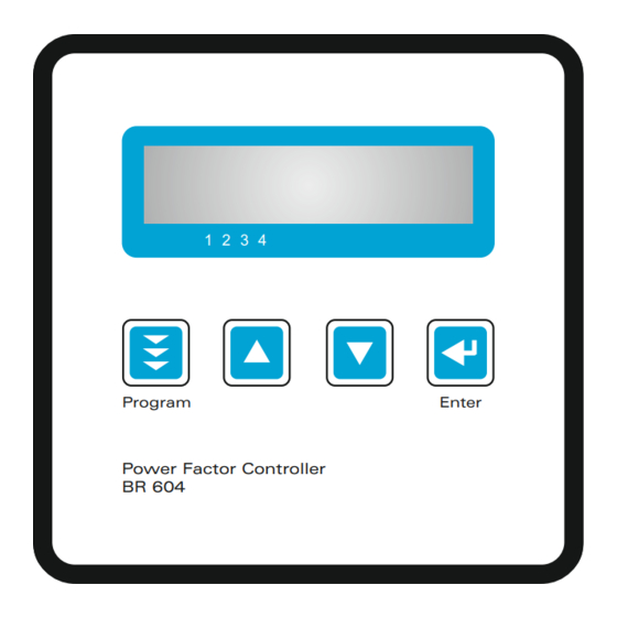
- Page 5 5A or 1A (programmable). A voltage converter is required for different operating voltages. Operating voltage = measuring voltage ! Caution! Voltages which exceed the allowed voltage range can damage the device ! Fig. 1 BR 604 front view Program Enter Power Factor Controller BR 604 Increase...
- Page 6 Section 2 Installation and connection of the controller The BR 604 is designed to be incorporated into the front panel of a PFC- cabinet. It requires a switchboard section of 92 x 92 mm to DIN 43 700. The controller is inserted from the front and is attached by means of the appended clamps.
-
Page 7: Current Measurement
The outputs of the compensation network must be installed behind the current converter (in the direction of current flow). If the BR 604 is connected up via sum- current converters, the overall conversion ratio is entered. -
Page 8: Fault Messages
MEASURING CURRENT < Section 3 Operating modes and programming When the operating voltage is switched on, the BR 604 briefly displays its designation and software version, then changes to its normal operating status (automatic operation). The active cos-phi value is always displayed in the upper line and the currently connected capacitors are shown as symbols in the lower line (operating display). -
Page 9: Automatic Operation / Display Functions
Manual (manual operation)- Service - Expert mode and back. 3.1 Automatic operation - display functions The BR 604 is set to automatic operation as standard. Capacitor stages are then automatically connected in or out in order to reach the target power factor. - Page 10 LANGUAGE SELECTION: This selects the language of the operating menu ( English, German, Spanish, Portuguese) ) 1 I-CONVERTER PRIM: This selects the primary current of the current converter. Adjustment is via the é / ê keys. (5...7500A) Save and continue with ENTER 2 I-CONVERTER SEC: This sets the secondary current of the current converter.(5A or 1A possible).
- Page 11 7 TARGET COS PHI: By setting the target cos phi, the power factor to be attained via the PF correction is defined. It is also set via the é / ê keys. The range may be selected from 0.3 inductive to 0.3 capacitive.
-
Page 12: Programming Lock
3.3 Programming lock The BR 604 is equipped with a programming lock to ensure protection from unauthorized or inadvertent changes to the system parameters. The lock can be activated in expert mode. If the lock is active, all parameters can be checked but not changed. -
Page 13: Manual Operation / Fixed Stages
Section 4 Manual operation, Programming of fixed stages m a n u a l o p e r a t i o n , c a p a c i t o r b r a n c h e s c a n connected/disconnected in the set control series and switching time - irrespective of prevailing power-line conditions. -
Page 14: Service Menu
Section 5 Service menu The service menu is reached by the operating-mode key. The stored maximum values of the network parameters can be displayed here. Action Display ENTER 1 max. VOLTAGE in V ENTER 2 max. REACTIVE POWER in kvar ENTER 3 max. -
Page 15: Initial Operation
PHASE I [0°] [L1] - L1 - N Adjustment of current phase position 4 PHASE V [0°] [L1 - N] Adjustment of voltage phase position Phase correction between voltage and current in the measuring system. (see table 1 at page 18) This setting allows to measure also in systems without neutral. -
Page 16: Control Principle
Section 8 Control principle The control response of the BR 604 can be selected in programming mode. In principle, the controller has 3 different control modes: 1. Sequential connection In sequential connection, the required capacitor stages are successively connected and disconnected in stages (last in - first out). -
Page 17: Troubleshooting
Section 9 Troubleshooting Check / Solution At target cos phi=1 and inductive Check terminals of the measuring voltage load, switch-off or connection of and current (l and k)! capacitor in the corrected line Check phase position Supply / Drawing mismatched Wrong line cos phi is Displayed Display:"UNDER CURRENT”... -
Page 18: Maintenance And Warranty
Section 10 Maintenance and warranty The BR 604 should need no maintenance if the operating conditions are observed. However, it is recommended that a functional check of the controller be performed in conjunction with the regular checking of the capacitor bank. In the event of any interventions in the controller during the warranty period, all warranty claims lapse. -
Page 19: Technical Data
Section 11 Technical data Outputs Switching power of relay 250 VAC, 1000 W Number of outputs Programmable Operation and display Graphic display 2 x 16 characters with convenient operating level No of control series Control principle Sequential connection, loop connection,self-optimized switching response, Four-quadrant operation... -
Page 20: Annex 2 Table Of Control Series
Annex 2: Table of control series Control series Loop connection 1 : 1 : 1 : 1 Possible 1 : 2 : 2 : 2 Possible 1 : 2 : 2 : 3 Possible 1 : 2 : 2 : 4 Possible 1 : 2 : 2 : 5 Possible... -
Page 21: Annex 3 Default Settings
Annex 3: Default settings Parameter Default setting LANGUAGE ENGLISH I CONVERTER prim. 1000 A I CONVERTER sec. END STOPP CONTROL SERIES CONTROL PRINCIPLE INTELLIGENT POWER 1. STAGE 25.00 kvar TARGET COS-PHI 0.98 IND SWITCH- IN TIME 40 sec. SWITCH- OFF TIME 40 sec. - Page 22 AUTO MODE cos =0.98 IND PROGRAMMING 3 4 5 6 7 8 9 10 11 12 In case of error alternating display between error and cos Phi LINE VOLTAGE LANGUAGE 400.0 V ENGLISH 2 APPARENT CURRENT I-CT PRIMARY 88.88 A [ 1000 ] A / X UNDERCOMPENSATED.
-
Page 23: Operating Diagram (Brief Programming)
BACK TO 1 TRIGGER VALUE BACK TO 1 [ 66 ] % SWITCH. POWER max [ ... ] kvar PROGRAM LOCK [ NO ] CONTROL [ 3 ] PHASE Operating diagram (Brief programming) BACK TO 2 Power Factor Controller BR 604...
Need help?
Do you have a question about the BR 604 and is the answer not in the manual?
Questions and answers