Table of Contents

Related Manuals for SpinCore Technologies PulseBlaster

Summary of Contents for SpinCore Technologies PulseBlaster
- Page 1 PulseBlaster - Programmable Pulse and Delay Generator (PCI Board SP17) (PCIe Boards SP35, SP40, SP41, SP44, SP46) Models: PB12-100-4k, PB24-100-4k, PB24-100-32k, PB24-100-64k Owner’s Manual SpinCore Technologies, Inc. http://www.spincore.com...
- Page 2 SpinCore Technologies, Inc. makes every effort to verify the correct operation of the equipment. This equipment version is not intended for use in a system in which the failure of a SpinCore device will threaten the safety of equipment or person(s).
-
Page 3: Table Of Contents
LabVIEW Extensions ....................14 PulseBlaster MATLAB GUI ..................15 C/C++ Programming ....................16 IV. Connecting to the PulseBlaster Board ..........18 Connector Information .................... 18 General Pin Assignments ..................18 DB25 Bracket Connector Flag 0..15 - Pin Assignments ........18 SMA Connector Clock_Out ................ - Page 4 Shrouded IDC Connector Flag24..26 - Pin Assignments ........21 Shrouded IDC Connector HW Trig/Reset ............22 Clock Oscillator Header ..................24 Appendix I: Controlling the PulseBlaster with SpinAPI ......25 Introduction ......................25 Instruction Set Architecture ................... 25 Machine-Word Definition ..................25 Breakdown of 80-bit Instruction Word ..............
-
Page 5: Introduction
A unique and distinguishing feature of the PulseBlaster processor is that the execution time of instructions is user programmable. This feature makes the PulseBlaster capable of executing complex output timing patterns at greatly varying update rates, ranging from nanoseconds to years, with a constant setting accuracy of just one clock period (e.g., a 10 ns setting accuracy at a 100 MHz clock... -
Page 6: Board Architecture
IBC over the peripheral component interconnect (PCI) bus. PCI Bus PCI Bus Figure 1: PulseBlaster board architecture. The clock oscillator signal is derived from an on-chip PLL circuit typically using a 50 MHz on-board reference clock. Key Features Output Signals The PulseBlaster PB24 models allow for 24 digital output signal lines. -
Page 7: Timing Characteristics
IDC connector pins labeled “Status”. The same output can be read through software using C. See Section IV (Connecting to the PulseBlaster Board, page 18) for more detail about the hardware lines and Appendix I (Controlling the PulseBlaster with SpinAPI, page 25) for more detail about the C function pb_read_status(). -
Page 8: Summary
RadioProcessor lines of boards still rely on the same PulseBlaster core for TTL pulse generation. Therefore, the basic example programs for the PulseBlaster will be able to produce the same results on any of the more complex boards. The exception is the PulseBlaster-DDS-II board which uses a 96-Bit or 124-Bit instruction word, depending on the firmware, instead of an 80-Bit instruction word and is currently not compatible with PulseBlaster methods of programming the board. -
Page 9: Ii. Installation
API will also install the necessary drivers. 2. Shut down the computer, unplug the power cord, insert the PulseBlaster card into an appropriate slot (PCI for PCI boards and PCIe for PCIe boards) and fasten the PC bracket securely with a screw. - Page 10 Figure 4 below shows a typical pattern displayed by an oscilloscope when running pb24_ex1.exe with the above described connections. Verifying this behavior confirms the board is installed properly. Figure 4: Expected signal from a PulseBlaster output running pb24_ex1.exe. http://www.spincore.com 2021/03/22...
- Page 11 PulseBlaster You may also run the remaining example programs available for this board to observe different output patterns and pulse durations. Keep in mind that pb24_programmable_clock.exe is only compatible with PulseBlasters with the programmable clock feature which is available upon request.
-
Page 12: Iii. Programming The Pulseblaster
Interpreter, LabVIEW extensions, .NET GUI, MATLAB GUI, and C/C++ methods of programming will be introduced. In addition to these, the PulseBlaster is programmable using nearly any higher level programming software that lets you utilize a C language API package, in this case SpinCore's SpinAPI. -
Page 13: Pulseblaster.net
Figure 6 shows an example instance of the program. Figure 6: An example pulse program in PulseBlaster.NET. This example creates a pulse that has all TTL bits on for 100 ms, alternating bits on for 400 ms (looping three times), and then all bits off for 100 ms. -
Page 14: Labview Extensions
The package contains basic subVIs, that can be used to include PulseBlaster interaction from your own LabVIEW programs, as well as some complete example VIs. Additionally, all of the examples are available as stand-alone applications, so that no programming is necessary for use. -
Page 15: Pulseblaster Matlab Gui
PulseBlaster would like to make a custom interface for the PulseBlaster board. For more information and downloads please visit: http://www.spincore.com/support/PBLV/TTL.shtml PulseBlaster MATLAB GUI PulseBlaster MATLAB GUI is a graphical interface for creating pulse programs and loading them to the PulseBlaster board. PulseBlaster MATLAB GUI currently provides the simplest interface possible to pulse control. -
Page 16: C/C++ Programming
PulseBlaster C/C++ Programming The most dynamic and flexible way to program the PulseBlaster board is with C/C++ using the SpinAPI package. While GUI's are easier to use, coding in C/C++ allows you to better utilize all features of the board, and in some cases it may be easier to copy and paste lines of code than to make 100 instructions on a GUI. - Page 17 PulseBlaster • The first is the hexadecimal 0xFFFFFF which corresponds to setting the 24 output bits to a logical high since it translates to a binary string of 24 1's. • The second parameter is CONTINUE which means to proceed on to the next instruction after this one completes.
-
Page 18: Iv. Connecting To The Pulseblaster Board
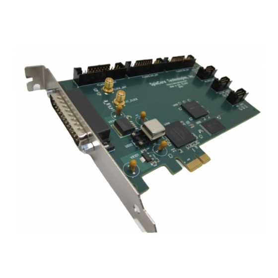
PulseBlaster IV. Connecting to the PulseBlaster Board Connector Information Figure 10: Sketch of PulseBlaster, Board Version SP17 On the SP17 board, the Clock_Out and Ext_Clk are SMA connectors, Flag0..15 is a DB-25 connector, Other versions of Flag0..11, Flag12..23, Flag24..26 and HW Trig/Reset are shrouded IDC header connectors. -
Page 19: Sma Connector Clock_Out
This SMA connector outputs the reference clock as a 3.3 V TTL signal, i.e., it generates positive- only voltage. Note that the PulseBlaster PCI and PCIe boards use 50 MHz as the reference clock frequency and that clock is internally multiplied to provide that actual PulseBlaster Core frequency The output resembles a square wave if properly terminated. -
Page 20: Sp17 And Pcie Boards Specific Pin Assignments
The shrouded IDC connector labeled Flag 12..23 can be connected to IDC-MMCX adapter boards (Figure 17, page 36) which allows the use of MMCX cables. This enables the individual bits of the PulseBlaster to be more easily accessed. Pin 1 on the MMCX adapter board can identified with a square pin. -
Page 21: Shrouded Idc Connector Flag24..26 - Pin Assignments
Reset – Driven high when the PulseBlaster device is in a RESET state and must be reprogrammed before code execution can begin again. Running – Driven high when the PulseBlaster device is executing a program. It is low when the PulseBlaster enters either a reset or idle state. -
Page 22: Shrouded Idc Connector Hw Trig/Reset
PulseBlaster Waiting – The PulseBlaster device has encountered a WAIT Op Code and is waiting for the next trigger (either hardware or software) to resume operation. Note that the Running bit will also be high during a WAIT state. Shrouded IDC Connector HW Trig/Reset This is an input connector, for hardware triggering (HW_Trigger) and resetting (HW_Reset). - Page 23 2V and 3.3V), then must be pulled low (to ground) and stay low for at least 10 ns before returning to high voltage. The PulseBlaster will continue to trigger or reset for as long as the HW_Trigger or HW_Reset signals stay at ground. If using a long TTL cable, make sure it is terminated and a buffer is used.
-
Page 24: Clock Oscillator Header
PulseBlaster Clock Oscillator Header The PulseBlaster comes with a crystal oscillator mounted on the oscillator socket to provide a timing signal for the board. If required, it is possible to remove the oscillator that comes standard, and instead drive the PulseBlaster with an external clock signal. The oscillator module can be removed from the board, and an external signal can be input through the header pins. -
Page 25: Appendix I: Controlling The Pulseblaster With Spinapi
This section provides detailed descriptions of the instruction set for the processor on the PulseBlaster board and the C functions in SpinAPI that utilize them. The information on the instruction set is very in depth and knowledge of this is essential to be able to properly operate the board. - Page 26 PulseBlaster The 80-bit VLIW is broken up into 4 sections: 1. Output Pattern and Control Word - 24 bits. 2. Data Field - 20 bits. 3. Op Code - 4 bits. 4. Delay Count - 32 bits. Output Pattern and Control Word Please refer to Table 6 for output pattern and control bit assignments of the 24-bit output/control word.
- Page 27 Delay Count field should account for this inherent delay. (NOTE: the pb_inst() family of functions in SpinAPI and the PulseBlaster Interpreter automatically account for this delay.) http://www.spincore.com...
-
Page 28: About Spinapi
PulseBlaster. It returns a 0 on success or a negative number on an error. int pb_close(); Releases PulseBlaster board. Needs to be called as last command in pulse program. It returns a 0 on success or a negative number on an error. - Page 29 PulseBlaster int pb_core_clock(double clock_freq); Used to set the clock frequency of the board. The variable clock_frequency is specified in MHz when no units are entered. Valid units are MHz, kHz, and Hz. The default clock value is 50MHz. You only need to call this function if you are not using a 50 MHz board which is reflected in the model (e.g.
- Page 30 SpinAPI. int pb_select_board(int board_num); If multiple boards from SpinCore Technologies are present in your system, this function allows you to select which board to communicate with. Once this function is called, all subsequent commands (such as pb_init(), pb_core_clock(), etc.) will be sent to the selected board.
-
Page 31: Example Use Of C Functions
PulseBlaster Example Use of C Functions * PulseBlaster example 1 * This program will cause the outputs to turn on and off with a period * of 400ms #include <stdio.h> #define PB24 #include "spinapi.h" int main(){ int start, status; printf ("Using spinapi library version %s\n", pb_get_version());... -
Page 32: Appendix Ii: Sample C Program
PulseBlaster Appendix II: Sample C Program * PulseBlaster example 2 * This example makes use of all instructions (except WAIT). #include <stdio.h> #define PB24 #include <spinapi.h> int main(int argc, char **argv){ int start, loop, sub; int status; printf ("Using spinapi library version %s\n", pb_get_version());... - Page 33 PulseBlaster // End of pulse program pb_stop_programming(); // Trigger the pulse program pb_start(); //Read the status register status = pb_read_status(); printf("status = %d", status); pb_close(); return 0; http://www.spincore.com 2021/03/22...
-
Page 34: Appendix Iii: Available Firmware Designs
PulseBlaster Appendix III: Available Firmware Designs The following table contains information about the various firmware designs available on the PulseBlaster series of boards. Firmware Board Clock Speed Number of Memory Depth Output Current Revision (MHz) Output Bits (words) Strength (mA) -
Page 35: Related Products And Accessories
This cable uses the parallel type DB-25 connector to easily access the TTL bits of the PulseBlaster Board. 2. PulseBlasterESR-PRO – Alternate version of the PulseBlaster that are capable of Higher Clock Frequencies (currently up to 500 MHz). For more information, please visit http://www.spincore.com/products/PulseBlasterESR-PRO/... - Page 36 6. SpinCore MMCX Adapter Board Figure 17 – This adapter board allows easy access to the individual bits of the PulseBlaster. This adapter board can be part of a package that includes 12 MMCX to BNC cables and three SMA to BNC adapters. This package can be changed to include any number of cables and any number of adapter boards.
- Page 37 PulseBlaster The SMA-BNC Adapter Board, shown in Figure 18, provides easy access to four additional output signals from the back panel of your computer. SMA-SMA cables are available from SpinCore upon request. For ordering information, please visit http://spincore.com/products/Adapters/ contact SpinCore at http://www.spincore.com/contact.shtml.
- Page 38 Figure 20: TTL Line Driver assures TTL levels over 50 Ohm loads. 8. If you require a custom design, custom interface cables, or other custom features, please inquire with SpinCore Technologies through our contact form, which is available at http://www.spincore.com/contact.shtml.
-
Page 39: Contact Information
PulseBlaster Contact Information SpinCore Technologies, Inc. 4631 NW 53rd Avenue, SUITE 103 Gainesville, FL 32653 Telephone (USA): 352-271-7383 Website: http://www.spincore.com Web Form: http://spincore.com/contact.shtml Document Information Page Revision history available at SpinCore. http://www.spincore.com 2021/03/22...
Need help?
Do you have a question about the PulseBlaster and is the answer not in the manual?
Questions and answers