Advertisement
Quick Links
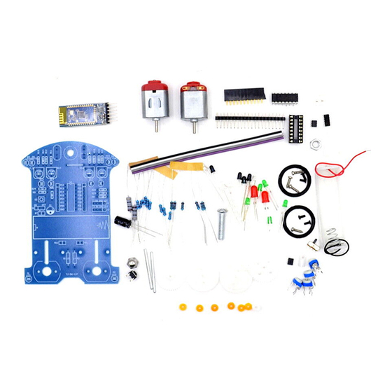
D2-6 kit instructions
Introduce:
D2-6 type bluetooth car kit is the latest version of D2 series kit, single-chip microcomputer
as the core, through program control achieves tracking, obstacle avoidance, Bluetooth mobile
phone control, gravity induction control functions.
The car with the serial interface, through the connecting the Bluetooth module to achieve
wireless remote control function.
Compared to the previous D2 series car can only control forward, D2-6 added more features,
not only can achieve forward, but also can be achieve fall back.
Lithium batteries, rechargeable, reduce the cost of use. (You need to prepare your own
battery, this kit has no battery)
Feature:
Operating voltage: DC 3.7V (one lithium battery)
Circuit board size: 105mm * 72mm
Various light-emitting diodes
3MM infrared emitting diodes. Part of the lamp beads transparent, long legs positive, short
legs negative
3MM infrared receiver diode, lamp beads part is black, long legs positive, short legs
negative.
3MM green light-emitting diodes, lamp beads part is green, green light. Long legs positive,
short legs negative.
5MM red light-emitting diodes, light beads part is red, red light. Long legs positive, short
legs negative.
Advertisement

Summary of Contents for yourDroid D2-6
- Page 1 D2-6 kit instructions Introduce: D2-6 type bluetooth car kit is the latest version of D2 series kit, single-chip microcomputer as the core, through program control achieves tracking, obstacle avoidance, Bluetooth mobile phone control, gravity induction control functions. The car with the serial interface, through the connecting the Bluetooth module to achieve wireless remote control function.
- Page 2 The above diodes in the car PCB installation location has the following symbols. Here is the cathode, Here is the negative, connect the long leg connect the short leg of the diode diode Color ring resistance 22 ohms 5% 470KΩ 1% If you are not sure the resistance, you can use a multimeter to measure before the installation.
- Page 3 SMD Integrated Circuit Learn to identify the first foot patch of IC Note that there is a small concave point The bottom of the small point is the first foot On the PCB, this pad connects to the first pin of the LM339 SMD integrated circuit L9110S Note that there...
- Page 4 On the PCB, this pad connects to the first pin of the L9110S Single - chip microcomputer STC15W201S Single-chip is inserted on the IC Block, the assembly IC base, we should pay attention to the IC Block has a semi-circular small gap This mounting gap should be aligned with the semicircular notch on the top of the PCB.
- Page 5 Note that there is a root fly wire connected with the resistance of the shear pin Backside of the picture...
- Page 6 www.banggood.com Two pairs of infrared diodes for tracking, the top and the caster vertex distance is about 2B: put a three-way sleeve into the axle...
- Page 7 www.banggood.com 2C: Insert a washer into the steel shaft next to the 3-way sleeve...
- Page 9 if the gap is too small will cause the wheel is not The center hole and the axle of the three-way sleeve should be parallel to each other, otherwise the wheel...
- Page 11 Solder the motor power cord The following is the debug section Infrared sensitivity adjustment...
- Page 12 Four adjustable Four light-emitting diodes are used for resistors are used for infrared reception sensitivity IR receiver sensitivity indication. adjustment Adjusts the sensitivity of the two infrared rays used for tracking Remove the microcontroller Car flat, first, a pair of infrared tube on the black track alignment, the figure is the D7 and D3 aligned black track...
- Page 13 Counterclockwise adjust the adjustable resistor R10 until the light-emitting diode D14 light, and then clockwise adjust the adjustable resistance R10, until the light-emitting diode D14 completely extinguished, it adjusted. Move this set of infrared rays between the black track and the white area. It can be seen that when the black track is aligned, the light emitting diode D14 is turned off, and when the white area is aligned, the light-emitting diode D14 is turned on.
Need help?
Do you have a question about the D2-6 and is the answer not in the manual?
Questions and answers