Table of Contents
Advertisement
Quick Links
Advertisement
Table of Contents

Related Manuals for EMFields AM-11


Summary of Contents for EMFields AM-11
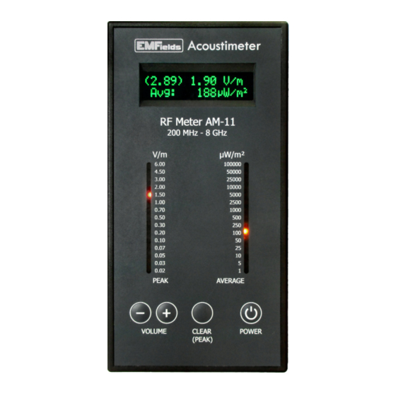
- Page 1 front high-res photo here Acoustimeter User Manual...
-
Page 2: Safety Instructions
This instrument is not intended to be serviced by the user, nor does it need any special maintenance. Unscrewing the case may void the guarantee. While EMFields considers that the information and opinions given here are accurate, you must rely upon your own skill and judgement when making... -
Page 3: Table Of Contents
Contents Safety Instructions ............2 Technical Specifications ..........4 Introduction ...............5 Layout of the meter ...........6 Operation and use ............7 Setting up for first use ........... 7 Taking measurements ........... 7 Audio ..............9 EMFs – What to measure? ........10 What are EMFs? ..........10 Electromagnetic spectrum guide ...... -
Page 4: Technical Specifications
Technical Specifications Typical frequency response using the internal antenna: 200 MHz – 8000 MHz ± 6dB ± 0.02 V/m Measurement Range: The LCD displays peak-hold, peak and average values. Updated about 2.5 times per second. Note: Peak Hold is reset/cleared using front button Peak readings: 0.02 - 6.00 V/m LED Scale: 15 levels, from 0.02 to 6 V/m Updated 5 times per second. -
Page 5: Introduction
Introduction The Acoustimeter will enable you to make quick and informed judgements regarding radiofrequency (RF) Electromagnetic Fields (EMFs) in your environment. The Acoustimeter measures all RF EMF sources from 200 MHz to 8000 MHz (8 GHz) which, in practical terms, covers most modern wireless communication RF signals that you will be exposed to. -
Page 6: Layout Of The Meter
Layout of the meter Key: 1. OLED Display 2. Peak signal LEDs 3. Average power LEDs 4. Volume controls (5 levels, - lower, + higher) 5. Clear (peak) hold button 6. Power button 7. Internal Antenna location 8. Loudspeaker 9. Battery compartment (for 2x AA cells) -
Page 7: Operation And Use
Operation and use Setting up for first use Ensure that the 2 AA batteries are correctly installed. Press the button. The LEDs display a moving POWER pattern and the OLED displays a start-up screen: “ Acoustimeter Initialising... ” The audio is off at start-up. Change the volume in pre-set stages by pressing the + and VOLUME... - Page 8 Ideally hold the meter as shown in the picture. Try to keep the Acoustimeter at least 30cm away from your body when taking readings. Keep your hands towards the bottom of the instrument. If you wish, the Acoustimeter can also be placed (preferably upright) on a surface.
-
Page 9: Audio
Some sound samples to help you identify different signals are available on: http://www.emfields-solutions.com/rf Most modern digital EMF sources are “pulsed”, meaning they have an amplitude-modulated signal. However, some sources are not amplitude... -
Page 10: Emfs - What To Measure
EMFs – What to measure? What are EMFs? EMF is usually taken to mean “time-varying electro- magnetic field” and cover an enormous spectrum of different phenomenon. These include, but are not limited to, “power frequency” fields (given off by any AC electrical device), mobile communication signals, TV and radio signals, military radars, infra-red, visible light, ultra-violet, x-rays and gamma rays. -
Page 11: Electromagnetic Spectrum Guide
Electromagnetic spectrum guide... -
Page 12: Guidance Levels
Guidance levels The most widely used exposure guidance is written by the International Commission on Non-Ionising Radiation Protection (ICNIRP). Their guidance levels are set to prevent tissue heating. This allows quite high-level exposures and it states that it is not intended to protect against cancer or any other low- level reported adverse health effects as they do not consider them to be adequately proven. -
Page 14: Various Exposures And Effects
BioInitiative Report. This was produced by some of the most highly experienced EMF/RF bio- effects researchers in the world. It can be read and downloaded here: www.bioinitiative.org We will also be maintaining up-to-date links with more information on our website: www.emfields-solutions.com/info... - Page 16 The Acoustimeter is designed specifically to measure the mostly used radio frequency (“RF”) part of the spectrum where our exposure has increased by an incredible amount over recent years and where most of the reported health-related concerns exist. Modern wireless communication frequencies (in the range from about 100 MHz to over 10 GHz) virtually did not exist on Earth just 100 years ago.
-
Page 17: Why Are There Two Different Readings
Why are there two different readings? We display two different types of reading, as they each represent different but important aspects of your exposure: Peak Signal Strength and Power Flux Density (PFD). Peak Signal Strength is the electric field strength, measured in volts per metre (V/m). - Page 18 V/m as well as the power in µW/m correctly integrated over some 25,000 readings every second. The EMFields website has an RF unit converter for continuous RF (CW) signals on this page: http://www.emfields-solutions.com/rf You may have noticed that different PFD units are used in some regions.
-
Page 20: Digital And Analogue Signals
Digital and Analogue signals Most modern wireless devices, such as mobile phones, Wi-Fi devices and cordless phones, use a digital system of communicating. This means they turn the signal on and off at high speeds to represent data, often with wide gaps between data bursts. - Page 21 A common example of a digital signal you are likely to be regularly exposed to would be DECT digital cordless phones or WiFi in your home environment. You can hear their ‘pulsing’ on the Acoustimeter. 4G is a “spikier” signal than 3G, and 5G has more sharp ‘pulses’...
-
Page 22: Typical Real-Life Exposures
Typical real-life exposures The AM11 has been tested in hundreds of situations. Although the highest sources in most homes are internal, some RF EMFs come from external sources. Indoor Domestic Readings Most homes have 4 major sources of RF EMFS: Cordless Digital (DECT) phones continuously produce fields of up to 4 V/m at 25cm, and around 1 V/m at 1m. - Page 23 External Readings Outdoors, readings vary a great deal. The most prevalent outdoor source of RF EMFs are mobile phone masts (base stations). Other external sources can include radar (occasional high blips of up to 6 V/m), Radio/TV transmitters (which may show high average power).
- Page 24 5G – Fifth Generation Mobile Phone systems 5G enables fast data speeds for critical applications. It will also connect billions of Internet of Things (IoT) devices. 5G Specifications include about 30 different bandwidths, modulation types and speeds. 4G-LTE is about 500 times faster than 3G. 5G and 5G-NR are about twice as fast as 4-LTE.
- Page 25 Smart meters These are utility meters that use RF to communicate with the supplier. Some are connected in a “mesh” network and communicate frequently. Some use a Mobile Phone network and transmit less often. Some (e.g. Linky) use Power-Line Communication (low frequency RF) and create a lot of “Dirty Electricity”...
-
Page 26: Troubleshooting
Troubleshooting The meter is not working Check that the batteries are correctly fitted and are not flat. If the OLED is displaying a reading, then the meter is turned on and working. The meter makes a loud double-beep Check for a “Low battery” screen message next time it beeps. - Page 27 The average power display does not match another instrument I have. Why is this? Some meters “convert” peak signals into an average power value which is misleading for modern signals. For digital signals this often results in a displayed power level considerably higher than the real PFD. The AM11 scales are correctly related to each other.
-
Page 28: Warranty
Please contact us to arrange a return if required. EMFields Solutions Ltd 12 Mepal Road, Sutton, Ely Cambridgeshire, CB6 2PZ, UK Email: info@emfields-solutions.com...
Need help?
Do you have a question about the AM-11 and is the answer not in the manual?
Questions and answers