Table of Contents
Advertisement
Quick Links
Advertisement
Table of Contents

Summary of Contents for Mortuary Lift Stepper ERGO
- Page 1 Operator Manual 2020 Edition...
-
Page 2: Table Of Contents
Contents Introduction and Features ---------------------------------------- 4 General safety instructions --------------------------------------- 5 Technical data of The Stepper® standard model ------------ 6 Technical data of the snap-on battery ------------------------- 6 Controls ---------------------------------------------------------------- 7 Diagram Front -------------------------------------------------------- 7 Diagram Back --------------------------------------------------------- 8 The swivel joint ------------------------------------------------------ 9 Control box ---------------------------------------------------------- 10 2.4.1 Button (P) for ascending/descending ------------------------- 10 2.4.2 Indicator light ------------------------------------------------------- 10... - Page 3 4.3.7 Driving on a winding staircase ---------------------------------- 20 Charging the Battery ---------------------------------------------- 20 Battery charger ---------------------------------------------------- 21 5.1.1 Testing --------------------------------------------------------------- 21 5.1.2 Charging ------------------------------------------------------------- 22 5.1.3 Protective features, technical data ---------------------------- 23 5.1.4 Safety rules ---------------------------------------------------------- 25 Accessories and Liability ----------------------------------------- 26 QuickStand----------------------------------------------------------- 26 Pouch (Body Bag) -------------------------------------------------- 29 Straps------------------------------------------------------------------ 31...
-
Page 4: Introduction And Features
Introduction and Features Congratulations! With The Stepper® you have purchased a handy modular- designed hand truck with an unladen weight of only 55 lbs. Once you fit the snap-on battery, this simple hand truck becomes a versatile all-a-rounder: a normal hand truck for general use on level ground and a powered stair climber for use on steps and stairs. -
Page 5: General Safety Instructions
General safety instructions In order to ensure that this product is used safely, be sure that you read and understand the following precautions fully and use the product only as directed. Be sure to read these Safety Instructions carefully before installing, connecting, operating, maintaining, or inspecting this product. -
Page 6: Technical Data Of The Stepper® Standard Model
Technical data of The Stepper® Model ERGO/UNI/FOLD Capacity 375 lbs. Maximum climbing 29 steps/min speed Weight 55 lbs. Maximum step 8.5” height Technical data of the snap on battery Fuse: Internal blow-out fuse (30 amps) Plug-socket for charger: DC jack ø 2.1 x 9.5 Weight: 9 lbs. -
Page 7: Controls
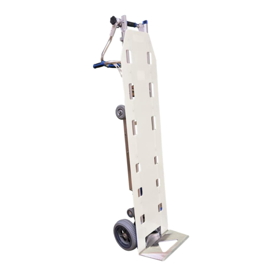
Controls Diagram – Front Control box Locking handle Holes for straps Body board Main wheels Folding foot plate... -
Page 8: Diagram Back
Diagram – Back Upper handle Ascending button (Q) Ascending button (R) (Swivel) Back handles Main power switch Drive unit Plug socket for charger Safety flap Swing arm with secondary wheels Snap on battery... -
Page 9: The Swivel Joint
The Swivel Joint Locking handle Swivel joint The necessary friction for the rotary joint is obtained through multiple friction disks, which are compressed simultaneously on the left and right sides. The lock must be tightened sufficiently to avoid movement in use. As a rule: The lock will be sufficiently tightened if a single operator can tilt back the load from the upright position without any handle movement. -
Page 10: Control Box
Control Box On/Off/Ascend/Descend/ button (P) Indicator light Speed switch 2.4.1 Button (P) for ascending/descending • Briefly press the push button to switch The Stepper® to ascent mode or descent mode. See section 4.1 Operation. • If the button is pressed for more than 3 seconds, The Stepper®... -
Page 11: Speed Switch
• Constantly red: The Stepper® is in descent mode and the support wheels move (fast) to the descend position (takes a max. of 0.5 seconds – refer also to chapter Operation [4.2]) • Flashing red: The Stepper® is overloaded. (Flashes for 3 seconds and goes out –... -
Page 12: Safety Flap
Safety flap To start tilting the load, it may be necessary to use your foot to assist in tilting. The axle of the conventional hand truck is normally used for this purpose. With The Stepper®, the swing arm with the support wheels, a wheel, or the drive unit may be used to support by foot. -
Page 13: Fitting And Removing The Battery
Fitting and removing the battery Fitting the battery (1) Locate corner “A” on both sides and hook into “B” on frame (2) Snap battery forward to engages locking hooks Removing the battery Battery must be lifted vertically to disengage locking hook. Do not hinge back. -
Page 14: Operation
Operation Ascending stairs Press button (P) briefly until the indicator light shines green continuously. The Stepper® is now in the UP MODE. Pressing the button (Q) or (R) in the upper handle or lower handle, will operate the support wheels and will lift The Stepper®... -
Page 15: Descending Stairs
Descending stairs Press button (P) briefly again until the indicator light flashes green. The Stepper® is now in the DOWN-MODE and the support wheels will move to the descend position automatically. The ascending buttons Q & R are now out of function. With the support wheels in the descend position The Stepper®... - Page 16 Important: As soon as The Stepper® rolls off the tread, ensure the main wheels are kept against the rise until the support wheels reach the descend position. Note: Just before the suspension arm reaches the descending position, the support wheels reach the upper edge of the stair and lift The Stepper®...
-
Page 17: Please Pay Attention To
Please pay attention to 4.3.1 Shift of balance When ascending the balance of the load changes as soon as the support wheels start lifting the load. Operators quickly become accustomed to this and compensate by tilting the handle. Initially, before this operation becomes automatic, care should be taken at the point where the support wheels take the load when ascending. -
Page 18: Overload
4.3.3 Overload DO NOT OVERLOAD Exceeding the load capacity will activate overload mode causing the operation to stop, lowering the main wheels slowly to the lower step. The indicator lamp flashes red for about 3 seconds after which the ascend/descend button will need to be reset. -
Page 19: Inadvertent Battery Ejection
4.3.5 Inadvertent battery ejection For all normal operations the battery is held securely by locking hooks. A strong pull is required to remove it. Abuse of The Stepper® by moving backwards very quickly, and striking a high step, or similar, will result in the batter being ejected from its location. -
Page 20: Driving On A Winding Staircase
4.3.7 Driving on a winding staircase When you must drive on a winding staircase please pay attention to the following: When ascending, The Stepper® tends to move to the inside of the staircase (any step a few inches depending on the angle of the winding). -
Page 21: Battery Charger
• The optimum temperature for charging is 68-77° F. Too cold or too warm has a negative effect on the capacity. Note: If the battery has not been fully charged or tends to lose charge too rapidly, this will not only reduce the speed of The Stepper®... -
Page 22: Charging
5.1.2 Charging (1) Connect the charging unit to the battery (2) The off-load voltage of the battery is shown on the display (3) Plug the charging unit into the mains (4) The charging operation begins The present charge status of the battery is symbolized by progress bars: Full, 100% Approx. -
Page 23: Protective Features, Technical Data
Display: Battery and the charge symbols blink alternately indicating a break in connection to battery, contact-fault check charging clips, cables, contacts, battery-pole terminals, etc. 5.1.3 Protective features, technical data Protective features Protection if the charging clips are short-circuited An electronic protection circuit prevents damage if the charging clips are short-circuited. - Page 24 Technical data Mains voltage (50/60 Hz, +/-15 %) 100-230 V AC Open-circuit power consumption max. 1.5 W Rated power output 48 W Charging voltage 24 V DC Arithmetic charging current with 230 V/ 50 Hz 2.0 A Degree of protection IP30 Time until safety cut-out 4.5 h...
-
Page 25: Safety Rules
5.1.4 Safety Rules Utilization for intended purpose only This battery charger is designed to charge lead storage batteries filled with liquid, get and AGM (absorbed glass mat) electrolytes only. This battery charger should never be used to charge NiCd and NiMH batteries and primary cells. Only use the unit if It is protected from direct sunlight and kept dry, and Cooling air can flow through the ventilation slots... -
Page 26: Accessories And Liability
Accessories QuickStand™ NEVER LEAVE LOAD UNATTENDED QuickStand™ IS NOT DESIGNED FOR LATERAL MOVEMENT Top lever Bottom lever Fig. A Stage 1 1. Pull and release top lever (Fig. A, B) 2. Apply firm grip to top handle (Fig. B) 3. Use legs to stand and raise The Stepper® continue raising The Stepper®... - Page 27 Fig. B Fig. C Stage 2 1. Adjust hand grip on top handle to a bicep curl position 2. Once load is secure, pull and release top lever 3. QuickStand™ will now be able to extend or collapse 4. Continue lifting until QuickStand™ locks into stage 2 (Fig.
- Page 28 Fig. D Stage 3 1. Adjust hand grip to back handles (Fig. D) 2. Push The Stepper® to a vertical position (Fig. E) 3. While securing and steadying the load, pull the bottom lever (Fig. A) then slide the QuickStand™ into collapsed position (Fig. F). Fig.
-
Page 29: Pouch (Body Bag)
Fig. F Pouch (Body bag) Attaching the pouch: (May use own pouch or one purchased from Mortuary Lift Company™) • Fasten the pouch to the top bar of The Stepper • (figure A) • Fasten the pouch through the holes in the white body board, near the bottom of The Stepper (figure B) •... - Page 30 Fig. B Body bag (pouch) holes: • Locate the holes on the backside of the pouch. • Straps may be slipped into and through the pouch or fastened over the outside of the pouch to secure remains. • When transferring remains from The Stepper® to a removal stretcher, grab side straps that are located down the entire length of each side of the pouch.
-
Page 31: Straps
Straps • From the front of The Stepper, insert the loop end of the strap through the hole in the white body board. • Then strap then loops around The Stepper frame and through the same hole in the white body board again. •... -
Page 32: Warranty And Liability
• Inadmissible modifications to the unit or accessory parts Liability Mortuary Lift Company™ is not responsible for the safety of The Stepper® if: • The Stepper® is used other than is intended • The Stepper® is not regularly (once a year) maintained by an authorized workshop •... -
Page 33: Ce Declaration Of Conformity
CE declaration of conformity Mortuary Lift Company™ declares that The Stepper® stair trolley corresponds to the applicable basic safety and health requirements of the CE Guidelines for machines 2006/42/EEC, appendix IIA. This declaration will lose its validity if changes are performed on the unit without our approval.
Need help?
Do you have a question about the Stepper ERGO and is the answer not in the manual?
Questions and answers