Table of Contents
Advertisement
Quick Links
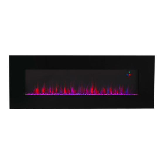
50" WALL MOUNT ELECTRIC FIREPLACE WITH GLASS
FIRESTONE
ITEM: 95029
OWNER'S MANUAL AND SAFETY INSTRUCTIONS
SAVE THIS MANUAL: KEEP THIS MANUAL FOR SAFETY WARNINGS, PRECAUTIONS, ASSEMBLY,
OPERATING, INSPECTION, MAINTENANCE AND CLEANING PROCEDURES. WRITE THE PRODUCT'S
SERIAL NUMBER ON THE BACK OF THE MANUAL NEAR THE ASSEMBLY DIAGRAM (OR MONTH
AND YEAR OF PURCHASE IF PRODUCT HAS NO NUMBER)
FOR QUESTIONS PLEASE CALL OUR CUSTOMER SUPPORT: (909) 628 0880 MON-FRI 9AM TO 3PM PST
Advertisement
Table of Contents

Related Manuals for Barton 95029


Summary of Contents for Barton 95029
- Page 1 50” WALL MOUNT ELECTRIC FIREPLACE WITH GLASS FIRESTONE ITEM: 95029 OWNER’S MANUAL AND SAFETY INSTRUCTIONS SAVE THIS MANUAL: KEEP THIS MANUAL FOR SAFETY WARNINGS, PRECAUTIONS, ASSEMBLY, OPERATING, INSPECTION, MAINTENANCE AND CLEANING PROCEDURES. WRITE THE PRODUCT’S SERIAL NUMBER ON THE BACK OF THE MANUAL NEAR THE ASSEMBLY DIAGRAM (OR MONTH...
-
Page 2: Important Safety Information
IMPORTANT SAFETY INFORMATION GENERAL SAFETY WARNINGS Read all safety warnings and instructions. Failure to follow the warnings and instructions may result in electric shock, fire and/or serious injury. Save all warnings and instructions for future reference. SAFETY WARNING DO NOT use this product or any available optional equipment without first completely reading and understanding these instructions and any additional instructional material such as owner’s manuals, service manuals or instruction sheets supplied with this product or optional equipment. - Page 3 IMPORTANT SAFETY INFORMATION DO NOT use the fireplace if any part has been under water. DO NOT operate the fireplace with the glass panel removed, cracked or broken. Servicing should only be done while the fireplace is disconnected from the power outlet. Unplug fireplace if not being used for an extended period of time.
-
Page 4: Package Contents
FEATURES Description Add a dash of romance to your home with the warmth and mesmerizing color play of this Fire and Ice electric fireplace. Its LED lights and crystals simulate flames dancing on embers while electric coils heat the surrounding air. There’s no smoke, no chimney, and no need to build or tend this fire. It is always under your remote control - as bright and as warm as you please. -
Page 5: Wall Mount Instructions
ASSEMBLY Getting Started: Unpack the contents of the box Heater Wall fixing bracket and screws Remote control 1 x bracket and and 1 x bottom bracket 8 x 6x25mm top bracket; 2 x 4*8mm to fix tempered glass 2 x 4*8mm and 1 x 6x25mm to fix the bottom 1 instruction manual 1 bag of crystal embers , 1 x white board Wall Mount Instructions... - Page 6 ASSEMBLY Remove the back panel from the heater first. See Fig 2 Fig. 2 Remove the two pieces of white screws on both sides on the heater. See Fig 3 Fig. 3 Drill holes with a #6 drill bit. Fix the wall bracket using the plug and 6x25mm screws provided. Carefully lift up the heater ensuring the top rear ledge of the heater engages with the wall bracket (see Fig.
- Page 7 ASSEMBLY Peel off the white board’s protective film and put the crystal on the appliance. Fig. 5 Place the front glass over the front of the fire aligning the slots in the bracket at each side of the glass panel with the lugs on the sides of the fire. Two people are required for this operatin. See Fig. 6 Fig.
- Page 8 ASSEMBLY Fasten two pieces of white screws of both sides. See Fig. 5 Fig. 5 The switches located at the center right hand side of the fire. The standby switch must be switched on first. Wall Insert Instructions Take the glass from the heater first then gently put the heater to the cut hole. This is a two person operation.
- Page 9 ASSEMBLY Place the front glass surround over the front of the aligning slots in each bracket at each side of the glass panel with the lugs on the sides of the heater. See. Fig. 4 Take the glass from the heater first then gently put the heater to the cut hole. This is a two person operation.
-
Page 10: Operation
OPERATION The heater can be operated either by the switches located in the top right side of the fireplace, or by the supplied remote control. Control Panel Access The Standby switch at the center right hand side of the foreplace must be first switched on. It takes time for the receiver to respond to the transmitter. -
Page 11: Replace The Remote Control Battery
MAINTENANCE The remote control requires one 3V CR2025 Lithium Cell Battery (included). Remove the protective film between the battery and the contacts in order to operate. See Fig 6 & 7 Replace the Remote Control Battery When the remote control stops operating or it’s range is reduced, it is time to replace the batteries. 1. -
Page 12: Please Read The Following Carefully
PLEASE READ THE FOLLOWING CAREFULLY THE MANUFACTURER AND/OR DISTRIBUTOR HAS PROVIDED THE PARTS LIST AND ASSEMBLY DIAGRAM IN THIS MANUAL AS A REFERENCE TOOL ONLY. NEITHER THE MANUFACTURER OR DISTRIBUTOR MAKES ANY REPRESENTATION OR WARRANTY OF ANY KIND TO THE BUYER THAT HE OR SHE IS QUALIFIED TO MAKE ANY REPAIRS TO THE PRODUCT, OR THAT HE OR SHE IS QUALIFIED TO REPLACE ANY PARTS OF THE PRODUCT.
Need help?
Do you have a question about the 95029 and is the answer not in the manual?
Questions and answers