Table of Contents
Advertisement
Quick Links
DATASHEET AND INSTALLATION MANUAL
DESCRIPTION
CD 475 offers reliable monitoring against attacks with me-
chanical tools. The CD 475 is a chock- and vibration detec-
tor with 3 separate detection channels: an integration
channel / saw channel for weak signals with long duration,
a counting channel that senses strong impact on the mon-
itored surface and an explosion channel which senses very
strong signals from e.g. an explosion.
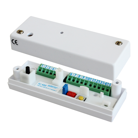
CD 475 shares the design with CD 470 but must be con-
nected to analyzer IU 400 for alarm indication since it lacks
built-in relay outputs. In the event of an alarm, the power
consumption in the detector increases, this is detected by
the analyzer IU400 which will indicate the different
alarms.
CD 475 polarity independent, just like CD 470.
FEATURES
EN Grade 3 approved vibration detector
Two wire polarity independent for easy connection
3 separate detection channels
Cover radius up to 3m
Resistant to interference
Detailed sensitivity setting
Suitable for 24 hour monitoring
Low power consumption
DAY and NIGHT control of LED
© 2020 Alarmtech
www.alarmtech.se
DETECTORS
Alarmtech reserves the right to changes
Chock- and vibration detector
OPERATING PRINCIPLE
The CD 475 uses a piezoelectric sensor to monitor the vibration
signature of the mounting surface that occurs when it is crushed
or cut with tools. The signal has a special signature with a broad
spectrum and high amplitude that the electronics detects, then
generates a current increase and illuminates the LED. The CD 475
has a built-in self-control and voltage monitoring. Fault is indi-
cated by a flashing LED and a pulsating current increase. The in-
dication is controlled by a DAY and NIGHT function. With 8Vdc
on the power input, DAY mode is active and LED lights up at
alarm and with pulsating shine in case of failure. At 6Vdc, NIGHT
mode is active and LED is switched off in case of alarm or error.
Resetting the detector after alarm can be done in two different
ways:
Disconnect power to the detector
Switch from DAY to NIGHT mode
MOUNTING
1.
Loosen the screw for the cover and lift it off.
2.
Select the mounting location and mark the mounting holes
with the bottom part as a template.
3.
Drill with a 2-2.5 mm drill for the two supplied mounting
screws.
NOTE! A clean and smooth mounting surface under the
detector provides maximum range.
CONNECTIONS
The detector has 2 screw terminals:
#
Function
1
DC Voltage supply (-) or (+)
2
DC Voltage supply (-) or (+)
CD475 manual 2003en
CD 475
Page 1 of 2
Advertisement
Table of Contents

Summary of Contents for Alarmtech CD 475
- Page 1 Switch from DAY to NIGHT mode strong signals from e.g. an explosion. CD 475 shares the design with CD 470 but must be con- MOUNTING nected to analyzer IU 400 for alarm indication since it lacks built-in relay outputs. In the event of an alarm, the power Loosen the screw for the cover and lift it off.
- Page 2 CD 475 LED until the number of pulses set is reached (3 or 6), then alarm is indicated. The alarm is indicated on the CD 475 LED and remains until the reset button on the IU 400 is pressed.
Need help?
Do you have a question about the CD 475 and is the answer not in the manual?
Questions and answers