Table of Contents
Advertisement
Quick Links
NANOSCAN OP400 QUICK START INSTRUCTIONS
ATTEMPTING TO USE THE NANOSCAN OP400 SYSTEM
IDENTIFYING YOUR SYSTEM COMPONENTS
The standard NanoScan OP400 system consists of:
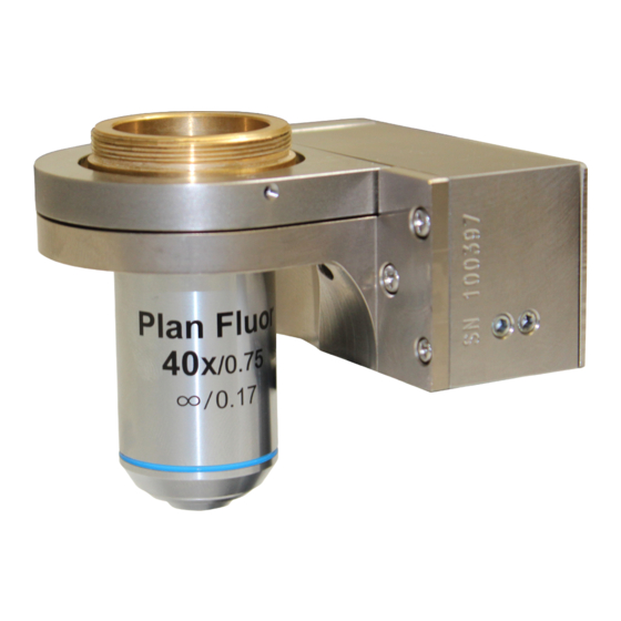
( 1 ) - NanoScan OP400 Piezo Objective Scanner
( 1 ) - NPC-D-6110 Controller and power supply
(1) - Microscope Thread Adapte
(1) - 1.3mm (0.05 inch) Hex Key + (1) tightening key
(
1) - Objective Lens Thread Adapter (optional)
(1) - Objective Lens Spacers (optional)
(1) - 9 pin gender changer for RS232C QG-0494-SK-200001
(1) - USB Cable QGPA0096-SK-102 + (1) 1.2 metre BNC to BNC
cable QGBNCCAB + (1) RS232C QG-0494-SK-200002
(1) - USB stick containing manuals and test
Please take care with the cabling. Under no circumstances use the cabling to hold the stage.
STEP 1: Select the position for the
OP400 on the nosepiece.
STEP 4: Insert the objective lens using the
appropriate objective lens adapter. Note no
adapter is necessary for M32. Other
objectives can be inserted into the nose piece
using option parfocal spacers.
P
R
T
LEASE
EAD
reports
INSTALLING YOUR SYSTEM
STEP 2: Insert the microscope thread adapter
using the key provided. Insert parfocal spacer
if other objectives are to be used.
INSTRUCTIONS BEFORE
HE
Tightening Key
www.prior.com
NanoScan OP400 Piezo
Objective Scanner
Microscope
Objective Lens
Thread Adapter
Thread Adapter
STEP 3: Connect the OP400 to the
nosepiece. Tighten both grub screws
with the hex key.
STEP 5: The OP400 unit
is now properly installed.
Gender
changer for
RS232C
Parfocal
Objective Spacer
Advertisement
Table of Contents

Summary of Contents for Queensgate NANOSCAN OP400
- Page 1 ATTEMPTING TO USE THE NANOSCAN OP400 SYSTEM IDENTIFYING YOUR SYSTEM COMPONENTS The standard NanoScan OP400 system consists of: ( 1 ) - NanoScan OP400 Piezo Objective Scanner ( 1 ) - NPC-D-6110 Controller and power supply (1) - Microscope Thread Adapte Gender (1) - 1.3mm (0.05 inch) Hex Key + (1) tightening key...
- Page 2 CONNECTING YOUR SYSTEM - FRONT OF UNIT IN POS Indicator LED POS MON connector Analogue COMS Indicator LED Indicates status of communications with connected Indicates the status of the stage position in CLOSED position monitor output BNC loop mode. connector(s) computer. Single ended output(s). OFF = Stage has not reached desired position.
- Page 3 SOFTWARE The standard customer-facing application for the system is called ‘Nanobench 6000’, and is included on the USB drive included in the shipment. This also includes software or links to software which must be installed before the software can be used. Visual C++ Runtime Labview Runtime Engine 2017 SPI F3 ‘Nanobench 6000’...
- Page 4 SOFTWARE Dynamic Setups The OP series stages come pre-loaded with ‘dynamic setups’, which allow the stage/controller to operate with a range of different objective loads, optimize step settle times and resolutions. To swap between these setups the controller must be unlocked to at least ‘User’ security. The setups can then be changed by selecting a new setup in the ‘Preset’...
Need help?
Do you have a question about the NANOSCAN OP400 and is the answer not in the manual?
Questions and answers