
Related Manuals for Wright Flow Technologies TR-IS Series


Summary of Contents for Wright Flow Technologies TR-IS Series
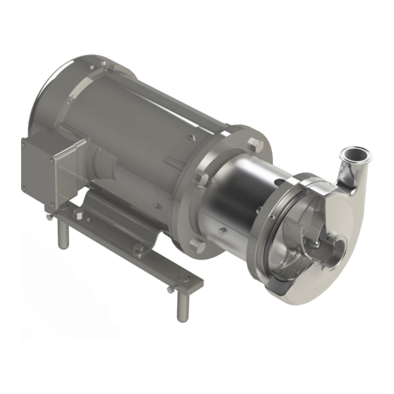
- Page 1 Installation, Operation, and Maintenance Manual TR-IS Series INTERNAL, BALANCED MECHANICAL SEAL CENTRIFUGAL PUMP 02-11...
-
Page 2: Table Of Contents
Thank you for purchasing a Wright Flow product! This manual contains installation, operation, cleaning, and maintenance instructions for the TR-IS Series. It also includes a parts list, a troubleshooting chart to assist in determining pump malfunction, and practical advice for the maintenance and operation of the equipment. -
Page 3: About This Manual
Wright Flow Technologies Warranty Wright Flow Technologies warrants all products manufactured by it to be free from defects in workmanship or material for a period of one (1) year from date of startup, provided that in no event shall this warranty extend more than eighteen (18) months from date of shipment from Wright Flow Technologies. -
Page 4: Safety
Centrifugal Pump IMPORTANT SAFETY INFORMATION Safety is very important! DO NOT attempt to modify any Wright Flow product! The TR-IS series centrifugal pumps have been designed to be safe and reliable. Any modifications could create unsafe conditions and void all warranties. -
Page 5: Installation
Before servicing pump, disconnect the electrical power source. The TR-IS series are closed-coupled pumps and are made up of two sections: power or drive section, and the liquid end or pump section. The pump is mounted to the frame of the drive motor by means of an adapter and is coupled to the motor shaft. -
Page 6: Assembly Preliminaries
OPERATION AND MAINTENANCE MANUAL TR-IS SERIES Centrifugal Pump ASSEMBLY PRELIMINARIES WARNING Before servicing pump, disconnect the electrical power source, carefully relieve all pressure, and drain all fluids from pump and connected piping. Before beginning the assembly procedure, identify every element that is going to be installed. -
Page 7: Tr-Is General Diagram
OPERATION AND MAINTENANCE MANUAL TR-IS SERIES Centrifugal Pump TR-IS GENERAL DIAGRAM TR-IS... -
Page 8: Tr-Is Part List
OPERATION AND MAINTENANCE MANUAL TR-IS SERIES Centrifugal Pump TR-IS PART LIST PART DESCRIPTION ITEM CASING CASING O-RING IMPELLER NUT PLUS IMPELLER NUT GASKET IMPELLER TR-IS MECHANICAL SEAL ROTARY HOLDER INTERNAL ROTARY FACE STATIC FACE EXTERNAL ROTARY FACE (DOUBLE MECHANICAL SEAL) -
Page 9: Start The Assembly
OPERATION AND MAINTENANCE MANUAL TR-IS SERIES Centrifugal Pump START THE ASSEMBLY It is highly recommended that the general diagram is used to help identify the components used in carrying out the assemblies and sub-assemblies that are explained below. 1. LEG BRACKET ASSEMBLIES The leg bracket assemblies are optional. -
Page 10: Assembling The Adapter To The Motor
OPERATION AND MAINTENANCE MANUAL TR-IS SERIES Centrifugal Pump 2. ASSEMBLY OF THE ADAPTER TO THE MOTOR Place the stainless adapter (15) on the motor flange and fasten it with hexagonal screws. Tighten to the torque values recommended in Chart 1. -
Page 11: Spacing Of The Impeller And Stub Shaft
OPERATION AND MAINTENANCE MANUAL TR-IS SERIES Centrifugal Pump 3. SPACING OF THE IMPELLER AND STUB SHAFT The correct operation of the pump depends on the separation of the impeller (5) from the backplate (7), and the fixation of the stub shaft (10) on the motor shaft. Follow the ensuing steps to install the stub shaft on to the motor shaft. - Page 12 OPERATION AND MAINTENANCE MANUAL TR-IS SERIES Centrifugal Pump Figure E Place only the rotary holder of the mechanical seal (6A) together with its respective O-ring (6H) until it seats on the shoulder of the stub shaft. Put the impeller key (12) on the keyway of the stub shaft.
- Page 13 OPERATION AND MAINTENANCE MANUAL TR-IS SERIES Centrifugal Pump Once the assembly is tightened, place a spacer between the back of the impeller and the front of the backplate. Use a spacer of 0.025” (0.63 mm) thru 0.030” (0.76 mm) for models 114, 214, 216 &...
-
Page 14: Assembling The Single Mechanical Seal
OPERATION AND MAINTENANCE MANUAL TR-IS SERIES Centrifugal Pump To remove the elements previously assembled, use the Ø3/8” plastic or soft dowel, the hexagonal socket, and wrench to untighten the impeller nut. Take the impeller nut, impeller gasket, impeller, and impeller key off. Do not forget to remove the spacer used to determine the stub shaft position. - Page 15 OPERATION AND MAINTENANCE MANUAL TR-IS SERIES Centrifugal Pump Internal Rotary Seal Sub-Assembly First, place the spring (6E) into the rotary holder (6A). The cut side must be centered with the pin inside the rotary holder. It is recommended to place the tips of the spring touching the rotary holder’s inside surface.
-
Page 16: Assembling The Double Mechanical Seal
OPERATION AND MAINTENANCE MANUAL TR-IS SERIES Centrifugal Pump Tighten the assembly as it is indicated in step 3c. For models 114 and 214 use a torque value of 25 ft.lb. For all other models, use a torque value of 40 ft.lb. Figure M. - Page 17 OPERATION AND MAINTENANCE MANUAL TR-IS SERIES Centrifugal Pump Place the stationary face of the mechanical seal (6C) with its O-rings (6J & 6K) into the backplate seal housing. First, place the O-ring (6J) on the stationary face groove, then the O-ring (6K) on the back.
- Page 18 OPERATION AND MAINTENANCE MANUAL TR-IS SERIES Centrifugal Pump Now, insert the whole rotary seal sub-assembly on to the stub-shaft. This will contact the stationary seal face previously placed in the backplate. Push to compress the assembly and then insert the impeller key into the stub-shaft. Place the O-ring (6G) onto the stub-shaft end; this O- ring seals between the stub-shaft, the rotary holder, and impeller.
- Page 19 OPERATION AND MAINTENANCE MANUAL TR-IS SERIES Centrifugal Pump Finally, place the racor flushes (9) on to the backplate; one on top and one at the bottom. It is recommended to feed clean water to the double mechanical seal with a pressure of 10 to 15 psi maximum.
-
Page 20: Assembling The Casing
OPERATION AND MAINTENANCE MANUAL TR-IS SERIES Centrifugal Pump 6. ASSEMBLING THE CASING Once the mechanical seal has been installed and the impeller and impeller nut assembly has been tightened, place the casing O-ring (2) onto the groove on the front of the backplate. Take the casing (1) and place it onto the adapter. - Page 21 OPERATION AND MAINTENANCE MANUAL TR-IS SERIES Centrifugal Pump Turn the impeller by hand and check that it does not rub against the casing. The assembly should turn easily without restriction. If there is any sound or sensation of rubbing, you need to check the whole assembly by disassembling and starting again.
-
Page 22: Common Problems
OPERATION AND MAINTENANCE MANUAL TR-IS SERIES Centrifugal Pump QUICK GUIDE FOR SOLVING COMMON PROBLEMS Wright Flow products are relatively easy to maintain. Just as with any other element of machines, problems may arise. This section offers a guide for identifying and correcting a majority of the pumping problems. - Page 23 Operation and Maintenance Manual Centrifugal pump TR-IS Series www.wrightflowtechnologies.com...
Need help?
Do you have a question about the TR-IS Series and is the answer not in the manual?
Questions and answers