Table of Contents
Advertisement
Operating instructions
Hydraulic rescue equipment
POWER UNITS
E/V 50 T-SAH 20, E/V 50 T-SAH 20 COAX, E/V 70 W-SAH 20, E/V 70 W-SAH 20 COAX,
E/V 400 S, V 40 S, E/V 50 S, V 50 ECO, V 400 ECO, V-ECOCOMPACT, E-COMPACT, V-ECOSILENT,
AKKUPAC ECO, B-COMPACT ECO, DPH/DPF 4018 SA, DPH 4018 S
8142459
Tested according to
EN 13204 and NFPA 1936
w w w.w e b e r - r e s c u e . c o m
Advertisement
Table of Contents

Summary of Contents for Weber Rescue Systems E 50 T-SAH 20
- Page 1 Operating instructions Hydraulic rescue equipment POWER UNITS E/V 50 T-SAH 20, E/V 50 T-SAH 20 COAX, E/V 70 W-SAH 20, E/V 70 W-SAH 20 COAX, E/V 400 S, V 40 S, E/V 50 S, V 50 ECO, V 400 ECO, V-ECOCOMPACT, E-COMPACT, V-ECOSILENT, AKKUPAC ECO, B-COMPACT ECO, DPH/DPF 4018 SA, DPH 4018 S 8142459 Tested according to...
-
Page 2: Table Of Contents
2 | Table of Contents Table of Contents General 1.1 Information regarding the operating instructions 1.2 Explanation of symbols 1.3 Limitations of liability 1.4 Copyright 1.5 Guarantee conditions 1.6 Customer service Safety 2.1 Proper use 2.2 Responsibility of the customer 2.3 Operating personnel 2.4 Personal protective gear 2.5 Specific hazards 2.6 Behaviour in the event of danger or accidents 2.7 Symbols Technical data 3.1 Operating conditions 3.2 Type plate Structure and function 4.1 Overview... - Page 3 Table of Contents | 3 Battery and charger (BATTERY PAC ECO, B-COMPACT ECO) 6.1 Charger technical data 6.2 Special safety instructions 6.3 Intended use 6.4 Power line connection 6.5 Li-Ion battery 6.6 Charging process 6.7 Maintenance 6.8 Charging cycles Transport, packaging and storage 7.1 Safety information 7.2 Transport inspection 7.3 Symbols on the packaging 7.4 Disposal of packaging 7.5 Storage Installation and commissioning 8.1 Safety information...
-
Page 4: General
4 | General 1 General Information regarding the operating instructions These operating instructions provide important information for using the hydraulic power units and hand pumps. Compliance with all of the safety and handling instructions specified is a condition for safe work. Furthermore, adhere to the local accident prevention guidelines and general safety regulations for the region in which the devices are used. The instruction manual should be read carfully before starting work! It is part of the product and must be kept in a place that is known and accessible to personnel at all times. This documentation contains information for operating your equipment, irrespective of the equipment type. For this reason you will also find explanations which do not refer directly to your equipment. All information, technical data, graphics and diagrams contained in these operating instructions are based on the most up-to-date data available at the time of writing. In addition to read through the operating instructions we also recommend that you be trained and instructed on handling the rescue equipment (possible applications, application tactics etc.) by our qualified trainers. -
Page 5: Explanation Of Symbols
General | 5 Explanation of symbols Warning instructions Warning instructions are marked by symbols in this operating manual. The individual instructions are introduced by signal words that express the degree of hazard. It is essential to comply with the instructions in order to prevent accidents, injuries and damage to property. DANGER! …indicates an immediate dangerous situation that can result in death or serious injury if it is not avoided. WARNING! …indicates a potentially dangerous situation that can result in death or serious injury if it is not avoided. CAUTION! …indicates a potentially dangerous situation that can result in minor or light injuries if it is not avoided. ATTENTION! …indicates a potentially dangerous situation that can result in material damage if it is not avoided. -
Page 6: Limitations Of Liability
6 | General Tips and recommendations NOTE ! …indicates useful tips and recommendations as well as information for efficient and trouble-free operation. Limitations of liability All information and instructions in this operating manual have been provided under due consideration of applicable standards and guidelines, the current state of technology, as well as our many years of knowledge and experience. The manufacturer assumes no liability for damage due to: • Failure to follow the operation instructions • Improper use • Use by untrained personnel • Unauthorized modifications • Technical changes • Use of non-approved spare parts • Use of non-original accessories The actual scope of delivery can vary from the explanations and graphic representations provided in this manual in the case of special versions, or due to technical changes. Copyright All text, diagrams, drawings and images in this operating manual may be used without restriction and without any prior approval. -
Page 7: Guarantee Conditions
General | 7 NOTE ! Further information, images and drawings can be found on our homepage. www.weber-rescue.com Guarantee conditions The guarantee conditions can be found as a separate document in the sales documentation. Customer service Our customer service department is available to you for technical information. Germany Name: Mr. Bernd Dürr Telephone: +49 (0) 7135 / 71-10530 Fax: +49 (0) 7135 / 71-10396 E-Mail: bernd.duerr@weber-rescue.com Austria Name: Mr. Robert Hack Telephone: +43 (0) 7255 / 6237-12473 Fax: +43 (0) 7255 / 6237-12461 E-Mail: robert.hack@weber-rescue.com NOTE! When contacting our customer service department please provide the designation, type and year of manufacture of your equipment. This information can be found on the equipment type plate. -
Page 8: Safety
8 | Safety 2 Safety This section of the operating manual provides a comprehensive overview of all the important safety aspects for optimal protection of operating personnel, as well as for safe and trouble-free operation. Significant hazards can occur if the handling and safety instructions in this manual are not complied with. WARNING! Danger when operating equipment with different operating pressures! Do not use pump power units with a higher operating pressure than the pressure that the rescue equipment is designed for (this can be seen on the type plate and in the operating instructions). Proper use The hydraulic power units are designed and tested exclusively for the appropriate designated purposes described here. All other activities are fundamentally prohibited. Power units (E/V 50 T-SAH 20, E/V 50 T-SAH 20 COAX, E/V 70 W-SAH 20, E/V 70 W-SAH 20 COAX, E/V 400 S, V 40 S, E/V 50 S, V 50 ECO, V 400 ECO, V-ECOCOMPACT, E-COMPACT, V-ECOSILENT, BATTERY PAC ECO, B-COMPACT ECO, DPH/DPF 4018 SA, DPH 4018 S) • All of the power units are designed as one-man devices and may therefore be operated by one person only. • These devices are designed exclusively for operating hydraulic rescue equipment from WEBER-HYDRAULIK. • Simultaneous operation of multiple pieces of equipment only if it is possible to exclude mutual risk. -
Page 9: Responsibility Of The Customer
Safety | 9 WARNING! Danger due to improper use! Any use of the equipment that exceeds the intended use or deviates from it can lead to dangerous situations! Therefore it is imperative that: » The equipment is used only for the purposes listed above. » Observe all other instructions in chapter 5 (operation) regarding appropriate use of the equipment. Responsibility of the customer In addition to the working safety instructions in this operating manual, observe safety and accident protection guidelines and environmental protection guidelines applicable to the area of application of the equipment. Particularly applicable in this regard: • The customer must inform himself of applicable industrial safety regulations and, within the framework of a hazard analysis, identify other hazards that may exist at the equipment‘s installation site due to the specific working conditions. • The customer must clearly regulate and specify responsibilities for installation, operation, maintenance, and cleaning. • The customer must ensure that all personnel who handle the equipment have fully read and understood the operating manual. • In addition, the operator must train personnel and inform them of the dangers of working with the machinery at regular intervals. Moreover, the customer is responsible for ensuring that the equipment is always in technically faultless condition. Consequently the following applies: •... -
Page 10: Operating Personnel
10 | Safety Operating personnel The following qualifications are cited in the operating manual for the various activity areas: • Trained person Is informed about the tasks assigned to them and the possible dangers in the event of improper behaviour through customer training. • Specialist Is an individual who, due to their specialized training, skills, and experience, as well as knowledge of the applicable manufacturer‘s regulations is capable of executing the tasks assigned to them and of recognizing possible hazards on their own. WARNING! Danger of injury due to insufficient training! Improper handling of the equipment can lead to serious injury or material damage. Therefore it is imperative that: » Particular tasks are only carried out by the personnel listed in the appropriate chapter of this instruction manual. » In case of doubt call in specialists immediately. NOTE ! The equipment may not be used by personnel who have consumed alcohol, taken medication or drugs! -
Page 11: Personal Protective Gear
Safety | 11 Personal protective gear Wearing personal protective equipment (PPE) is essential to minimize the risks to operating personnel when working with the power units. It is essential to wear the following protective clothing for all work: Protective work clothing Tight-fitting work clothing with tight sleeves and without projecting parts should be worn for work. It is primarily used to protect against entanglement by moving equipment parts. Safety footwear Safety footwear with steel toecaps must always be worn as protection against heavy falling parts and from slipping on slippery ground. Work gloves Work gloves must be worn when working with the equipment for protection against sharp edges and glass fragments. Helmet with face shield A helmet with face shield must be worn for protection against flying or falling parts and glass fragments. Protective goggles Protective goggles must also be worn in addition to the face shield in order to protect the eyes from slivers. With certain work the following must also be worn in addition: Ear protectors In addition to the basic protective equipment, ear protectors should also be worn for protection against hearing damage. -
Page 12: Specific Hazards
12 | Safety Specific hazards The hazards that arise within the framework of the risk evaluation are listed in the following section. Follow the safety instructions listed here and the warning instructions in the other sections of this manual to minimise potential health hazards and avoid dangerous situations. Electric shock DANGER! Life-threatening danger due to electric shock! There is an imminent life-threatening danger if live parts are touched. Damage to insulation or to specific components can pose a life-threatening danger. Therefore: » Disconnect the power supply immediately if there is damage to the insulation and have it repaired. » Only a qualified electrician should perform work on the electrical equipment. » All electrical work on the system must be carried out with the system disconnected from the mains power supply and the system must be check to confirm that it is de-energised. » Prior to any maintenance, cleaning or repair works the power supply must be switched off and secured against being unintentionally switched back on. » Do not bypass fuses or render them inoperable. Always use the correct amperage when changing fuses. » Keep moisture away from live parts. Moisture can lead to a short circuit. - Page 13 Safety | 13 Noise WARNING! Hearing damage due to noise! The noise occurring in the work area can cause severe hearing damage. Therefore: » Also wear ear protectors when carrying out particularly noise- intensive works. » Do not stay in the hazardous area longer than necessary. Hydraulic energy WARNING! Danger due to hydraulic energy! Serious injuries can be caused by discharged hydraulic force and the emergence of hydraulic oil. Therefore: » Always keep your eyes on the hydraulic equipment throughout the working process and set down if necessary. » Check the hoses and the equipment for damage after every usage. » Avoid skin contact with the hydraulic oil (wear protective gloves). » Remove hydraulic oil from wounds without delay and seek medical attention immediately.
-
Page 14: Behaviour In The Event Of Danger Or Accidents
14 | Safety Behaviour in the event of danger or accidents Preventative measures • Always be prepared for accidents • Keep first aid equipment (first-aid box, blankets etc.) to hand • Familiarize personnel with accident alarms, first-aid kits, and rescue equipment • Keep entry ways clear for rescue vehicles In the event of an accident • Shut down the equipment immediately • Initiate first-aid measures • Get people out of the danger zone • Inform the responsible parties at the implementation site • Notify a physician and/or the fire department • Keep entry ways clear for rescue vehicles... -
Page 15: Symbols
Safety | 15 Symbols The following symbols and instruction signs are found on the equipment. These symbols and instructions refer to the immediate vicinity in which they are affixed. Comply with the instructions in the operating manual Do not use the marked equipment until after you have read the operating manual. Warning of hot surface The power unit‘s engine can become very hot during operation. Therefore, do not touch it and wear protective gloves. WARNING! Danger of injury due to illegible symbols! Over time, stickers and symbols on the equipment can be become fouled or can become illegible in some other manner. Therefore it is imperative that: » Keep all safety, warning, and operating instructions that are affixed to the device in good, legible condition. » Replace damaged signs and stickers immediately. -
Page 16: Technical Data
16 | Technical data 3 Technical data E/V 50 T-SAH 20 E/V 50 T-SAH 20 COAX E/V 70 W-SAH 20 (COAX) E/V 400 S (ECO) V 50 ECO E/V 50 S / V 40 S... - Page 17 Technical data | 17 V-ECOCOMPACT V-ECOSILENT E-COMPACT B-COMPACT ECO AKKUPAC ECO DPH/F 4018-SA (S)
- Page 18 18 | Technical data E 50 T-SAH 20 V 50 T-SAH 20 E 50 T-SAH 20 COAX V 50 T-SAH 20 COAX Length 830 mm 838 mm 830 mm 838 mm Width 440 mm 440 mm 440 mm 440 mm Height 470 mm 470 mm 470 mm 470 mm Weight 75 kg 72 kg...
- Page 19 Technical data | 19 E 400 S V 400 S V 400 ECO E-COMPACT Length 413 mm 382 mm 382 mm 415 mm Width 288 mm 290 mm 290 mm 195 mm Height 385 mm 406 mm 406 mm 214 mm Weight 20,5 kg 17,4 kg 17,5 kg 12,2 kg Engine Eletrical engine 4-stroke petrol engine 4-stroke petrol engine Eletrical engine 230 V, 50 Hz, 0,5 kW 1,5 kW 1,5 kW 230 V, 50 Hz, 1,5 kW...
-
Page 20: Operating Conditions
20 | Technical data V-ECOSILENT AKKUPAC ECO B-COMPACT ECO DPH/DPF 4018 SA DPH 4018 S Length 590 mm 335 mm 515 mm 650 mm 729 mm Width 295 mm 250 mm 200 mm 255 mm 200 mm Height 445 mm 315 mm 314 mm 183 mm 183 mm Weight 24,9 kg 11,2 kg** 12,0 kg** 14,6 kg 9,9 kg Engine 4-stroke petrol DC motor DC motor... -
Page 21: Structure And Function
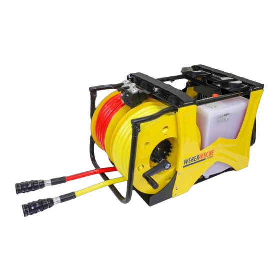
Structure and function | 21 4 Structure and function 4.1 Overview 1 Coupling 7 Electrical power connection 2 Hose reel 8 Carry handle (front) 3 Equipment brackets 9 Hydraulic oil tank 4 Control lever (red hose) 10 Frame 5 Control lever (yellow hose) 11 Carry handle (rear) 6 Engine Brief description Hydraulic power units serve the operation of the associated hydraulic rescue devices. They are available with an electrical engine and with a combustion engine. Furthermore, one differentiates between equipment with and without integrated rapid deployment reels and compact power units. With almost all units, two devices can be operated at the same time, or one device in turbo mode. On the hose reel, there are two hoses (available as a pair or as a COAX hose), one 15 m and the other 20 m long, that can be unrolled effortlessly even under pressure. -
Page 22: Hydraulic Supply
22 | Structure and function Hydraulic supply Hoses The connection of the device with the power unit is carried out via high pressure hoses. Hoses are available in lengths of 5 m, 10 m, 15 m and 20 m. As the length of the lines increases so too does the associated pressure loss. With a line length of 50 metres this pressure loss remains acceptable and has no significant effect. CAUTION! Do not use damaged hoses! With damaged hoses there is a danger of escaping hydraulic medium under pressure, or of the hoses whipping around. Therefore: » The hoses should be subjected to a visual inspection (leak- tightness, surface damage such as kinks) after every use and at least once per year. » Every three years, or in the event of doubts about the safety or reliability, carry out an additional functional and load test (as per DGUV Grundsatz 305-002 or specific national directive). » Replace hoses every 10 years! The date (code letters or quarter/year) is specified on the hose bonding. » Ensure that the hoses are not exposed to tension or torsion (turning). » Do not kink the hoses or draw them over edges (smallest bend radius 40 mm). » Do not subject the hoses to high temperatures. »... - Page 23 Structure and function | 23 Hydraulic oil All power units are designed and tested for WEBER hydraulic oil Part no. 804932. This oil possesses a particularly high purity level and also works flawlessly at temperatures below zero, down to -20° C. With limitations in the low temperature range (lower output), however, a standard oil (mineral based) of viscosity class HLP 10 or HVLP 10 can be used in keeping with DIN 51502. NOTE ! We recommend the following hydraulic oils for trouble-free operation of WEBER RESCUE devices: » AERO Fluid 41 (Shell) » Univis HVI-13 (Esso) » Aero-hydraulic 520 (Total) » Hydraulik DB (Castrol) » Renolin/MR310 (Fuchs) » HVI Extra 380 (Maier & Korduletsch) » Hydrex Arctic 15 (Petro Canada) » Naturelle HFE 15 (Shell) Oil level indicator There is a sight glass located on the side of the oil tank, with which the oil level can be monitored. This must be checked regularly after every use. The oil must be topped up if required.
-
Page 24: Equipment Connections
24 | Structure and function Equipment connections SINGLE coupling Connecting: Remove the protective cap from the coupling male and the coupling female (Fig. 1). Conflate Single coupling male and female in the bayonet catch (Fig. 2). Hold coupling female on the black slew ring and turn clockwise until the coupling snaps in (Fig. 3). Put protective caps together (Fig. 4). You don’t have to switch the power unit to position 0 to connect or disconnect the coupling! Disconnecting: Remove the protective caps. Hold coupling female on the black slew ring and turn anticlockwise direction. Turn the black slew ring until you can release the coupling easily. Put protective caps to coupling male and the coupling female. Fig. 1 Fig. 2 Fig. 3 Fig. 4 NOTE ! When using the SINGLE coupling, pressure relief connectors are no longer required. - Page 25 Structure and function | 25 Plug-in coupling (SKS) Connecting: Remove the protective cap from the coupling male. Take hold of the coupling female by the knurled sleeve cover and pull out the protective plug. With one hand take hold of sleeve cover of the coupling female, with the other grasp the coupling male (black) by the hex nut, and press the sleeve cover slightly against the coupling male until the ball bearings engage. Twisting the male coupling slightly when pressing togehter eases the coupling process. Disconnecting: Grasp the coupling male (black) by the hex nut with one hand and with the other take hold of the sleeve cover and draw it back. The disconnecting will cause a few drops of hydraulic oil to escape. Plug in the protective caps immediately. CAUTION! When coupling SKS connections the power unit operating lever must be in the „0“ position. NOTE ! A pressure relief connector is fitted to the hydraulic power units and the hand pump, with which a few drops of oil can be discharged from the hoses. This permits re-coupling following pressure increases in de- coupled equipment. In this case simply insert the pressure relief connector into the coupling sleeve and turn the knurled screw to the right until oil leaks out.
-
Page 26: Operation
26 | Operation 5 Operation General To start the unit with an electric motor, the device must be connected to a power source. Then set the main switch (if present) to position 1 or press the corresponding knob until it lights up white. For starting units with combustion engines, please read the accompanying operating manual from the engine manufacturer. Special steps for starting the individual units are discussed separately below. CAUTION! When using SKS couplings the engine must never be started before the control lever is out of the „0“ position and the work equipment is connected! With single couplings this is not necessary. E/V 50 T-SAH 20, E/V 50 T-SAH 15 COAX, V 40 S, E/V 50 S, V 50 ECO, V-ECOCOMPACT The power unit is operated by the two control levers (between the equipment brackets). The oil flow in the two hose sets is controlled by these. The middle position of the control levers represents the „0“ position. Two-way operation (with turbo function): In order to feed the entire oil flow into the left hose pair, both control levers must be turned to the left. -
Page 27: E/V 70 W-Sah 20, E/V 70 W-Sah 20 Coax
Operation | 27 Simultaneous operation: In order to supply both hose pairs simultaneously (with split oil flow), the left control lever must be turned to the left and the right control lever must be turned to the right. NOTE! The oil flow is likewise split if one lever is operated and the other remains in the „0“ position. It is therefore necessary to operate both control levers for the turbo function. E/V 70 W-SAH 20, E/V 70 W-SAH 20 COAX To start the electrical version of the device, actuate the ON/OFF switch (knob) located between the two reels. The signal light on the ON/OFF switch then lights up in white and the motor starts automatically. Two-way operation (with turbo function): In order to feed the entire oil flow into the left hose pair, both control levers must be turned to the left. In order to feed the whole oil flow into the right hose pair, both control levers must be turned to the right. Simultaneous operation: In order to supply both hose pairs simultaneously (with split oil flow), the left control lever must be turned to the left and the right control lever must be turned to the right. -
Page 28: E/V 400 S, V 400 Eco
28 | Operation E/V 400 S The power unit is operated by the control lever (adjacent to the connection for the high pressure hose). The oil flow in the hose pair is controlled by this. The control lever position perpendicular to the equipment (on „0“) represents the „0“ position. To operate, simply turn the control lever in the direction of the arrow. This initiates the oil flow in the hose pair. 5.5 BATTERY PAC ECO The BATTERY PAC can be carried on the shoulder or used as an independent stand-alone battery powered power unit. In order to start the device it is necessary to actuate the on/off buton on the top of the housing (Fig. 1). The signal light on the on/off switch subsequently lights up in white and the BATTERY PACK starts automatically in ECO mode (idle speed). Only after pressing the pushbutton on the connected work tool does the speed increase automatically and then decrease again. This saves energy (runtime in ECO mode of 5 hours per battery) and avoids unnecessary noise. Fig. 1 You can operate the unit with one battery or with two batteries operating in parallel (batteries are then drained parallel as well). The battery is inserted into the battery compartment. Simul- taneously pressing the unlocking mechanism releases the battery from the unit. -
Page 29: V-Ecosilent
Operation | 29 The coupling can be stored in the side pocket (Fig. 2). After use the hydraulic fluid level should always be between Min. and Max. so that all of the units can be operated, as the nominal pressure and tank content are designed to operate all WEBER rescue equipment. The oil tank can be filled / drained very easily by retracting or expan- ding a rescue tool (Fig. 3). Fig. 2 Fig. 3 V-ECOSILENT To start the power unit the yellow ECO lever must first be set to the start position („S“). Then turn the the ignition switch (rotary switch) to the right to „Choke“ and start the engine with the pull-chord. After warming up turn the ignition switch to position „1“ and set the ECO lever to „ECO“. Control In order to control the outputs, two control levers are fitted directly above the couplings. It is possible to control the oil flow with these (by sliding to the side; similar to E/V 50-T). Fuel tap When transporting the power unit for an extended period the fuel feed can be shut off. In order to do so it is necessary to close the fuel tap (red). This is located under the maintenance cover on the pull- chord side. Petrol tank The petrol tank can be filled via the filling port under the black cover flap on the top side of the device. The fuel level can be seen on the display on the operator panel. -
Page 30: E-Compact
30 | Operation E-Compact Operation Before starting the electric engine, check that all electrical connections and cables are in proper order. Insert the plug into a 230 V socket. Press the ON/OFF switch on the top of the unit. The unit starts automatically and a green LED lights up. Connect the hose and set the control lever to position 1. The unit is now ready to operate. Service instruction The “Attention” LED (RED) will light up under load after about 200 operating hours. After that, the unit can be used for another 10 to 20 operating hours before the electric motor’s carbon brushes need to be changed. This must be done by a qualified person. 1 ON/OFF button 2 LED attention (red) 3 LED operation (green) 4 Oil filling plug (Weber hydraulic oil) 5 Control lever... -
Page 31: B-Compact Eco
Operation | 31 5.8 B-COMPACT ECO Operation One battery as a minimum, or a 230V power supply, must be connected for the purpose of operation. Press the on/off button on top of the unit to switch it on (button lights up in white and the motor starts in ECO-mode). Subsequently connect the hose and set the control lever to position 1 (see page 30). The unit is now ready for operation. When the unit is switched on the LEDs mounted on both sides are also simultaneously activated, so that the unit can also be used as a portable spotlight en route to the installation site. Only after pressing the pushbutton on the connected work tool does the speed increase automatically and then decrease again. This saves energy (runtime in ECO mode of 5 hours per battery) and avoids unnecessary noise. Battery operation The B-COMPACT can be optionally operated using one battery, two batteries or a power supply. Both power sources are always drained in parallel here, whilst the speed or capacity of the unit is not affected by this. It is possible to remove the battery from the device again by simultaneously pressing the two lock releases. DPH/DPF 4018 SA (hand pump) In order start up the hand pump, first turn the pressure relief valve counter-clockwise and operate the pump lever a few times. This exhausts the air from the pump. Finally, turn the pressure relief valve fully in a clockwise direction and do not open it again during subsequent work with the equipment! It is now possible to initiate the oil flow to the rescue equipment by actuating the pump lever. -
Page 32: Battery And Charger (Battery Pac Eco, B-Compact Eco)
32 | Battery and charger 6 Battery and charger (BATTERY PAC ECO, B-COMPACT ECO) 6.1 Charger technical data technical data Charger MCLi Voltage range 28 V Charging current, quick charging 3.5 A Charging time ca. 1 h Weight w/o power cable 700 g Inputvoltage ID-No. 220/240V AC 50/60Hz (Europe) 1054097 240V AC (Australia) 1054098 110V AC (USA) - Page 33 Battery and charger | 33 WARNING! Important safety information concerning the battery and charger. » Do not use the charger to charge non-rechargeable batteries. » Do not store batteries together with metal objects (danger of short circuit). » Do not allow metal parts to enter the charger's battery insertion slot (danger of short circuit). » Do not open batteries and chargers, and store only in dry rooms. Protect from moisture. » The charger carries voltage from the power grid. Do not reach into the device with conductive objects. » Do not load a damaged battery — replace it immediately instead. » Before every use, check the device, connection cable, battery pack, extension cable and plug for damage and ageing. Allow only qualified personnel to repair damaged parts. » This device is not designed for use by persons (including children) with limited physical, sensory or mental abilities, or lacking experience, and/or lacking expertise, unless they are supervised by a person responsible for their safety or have received instructions from this person on how to use the device. Children should be supervised to ensure that they do not play with the device.
-
Page 34: Intended Use
34 | Battery and charger 6.3 Intended use This charger charges the 28V Li-ion battery of the M 28/V28 system delivered with the battery- powered devices. This device must be used only as specified and intended. Power line connection Only connect to single-phase AC current and only to the line voltage specified on the type plate. Connection to power sockets without an earthing contact is possible, because this is a protection class II design. Li-Ion battery For safety reasons (air transport regulations), the batteries are delivered uncharged. Before first use, the battery must be completely charged. LED charge status display Figure 1 If the battery is not used for a prolonged period of time, the battery switches to standby mode. To use again, the battery must be reactivated (recharged). The charge status can be called up by pressing the button on the battery (see Fig 1). To do this, the battery can remain in the battery-powered device, but it must be switched off at least 1 minute beforehand (otherwise the display will not be accurate). The number of glowing LEDs indicates the charge status. The basic principle is: If the battery-powered device does not function after the battery is inserted, put the battery onto the charger for testing. The displays on the battery and charger give information about the battery charge status. At low temperatures, the work can be still be carried out with lower performance. For best operational readiness, the batteries must be fully charged after use. -
Page 35: Charging Process
Battery and charger | 35 Charging process After inserting the battery into the charger's insertion slot, the battery is charged automatically (red LED glows continuously). If too warm or cold a battery is inserted into the charger (red LED flashes), the charging process starts automatically as soon as the battery has reached the correct charging temperature (0°C to 65°C). The maximum charging current flows if the temperature of the Li-ion battery is between 0°C and 65°C. The charging time is between 1 min. and 60 min., depending on how much the battery has drained (at 3.0 Ah). The charge time for the 5.0 Ah rechargeable battery lies between 1 min and 90 min. If the battery is fully charged, the LED on the charger switches from red to green. The battery does not need to be removed from the charger after charging. The battery can continue to stay in the charger. This cannot overload the battery, and it keeps the battery ready to use. If both LEDs flash alternately, the battery is either not correctly placed or a malfunction of either the battery or charger has occurred. For safety reasons, remove the charger and battery from service immediately and have it checked by an authorized customer service centre. flashing alternately! If the power adapter is overloaded, all LEDs flash 4 times. To be able to continue charging, unplug the power adapter and plug it back in. flashing simultaneously! -
Page 36: Maintenance
36 | Battery and charger Maintenance If the power cable is damaged, it must be replaced by a customer service centre. Use only approved accessories and replacement parts. Parts whose replacement has not been described must be replaced by an authorised customer service centre. Charging cycles Information Explanation Charging cycles approx. 1000 Partial discharge No effect, because the battery always retains its capacity until discharge. Partial discharge and subsequent Each recharge counts as a full charging cycle. Therefore recharge the battery should be used until completely drained. Deep discharge protection is provided... -
Page 37: Transport, Packaging And Storage
Transport, packaging and storage | 37 7 Transport, packaging and storage Safety information CAUTION! Incorrect transportation can cause damage! Significant material damage can occur due to incorrect transportation. Therefore: » Proceed with caution when unloading packages and observe the symbols on the packaging. » Do not open fully or dispose of packaging until at the intended storage location. Transport inspection The delivery should be checked immediately upon receipt for completeness and any possible transportation damage, so that a quick remedy can be instigated if necessary. In the event of visible external damage proceed as follows: • Do not accept the delivery, or only accept it with reservation. • Note the extent of transport damage on the transport documents or on the transport company‘s delivery note. • Submit a complaint. NOTE ! Report any defect as soon as it is detected. -
Page 38: Symbols On The Packaging
38 | Transport, packaging and storage Symbols on the packaging Caution fragile! Handle the package carefully, do not drop, throw, strike or tie up. This way up! The package must be transported and stored strictly such that the arrows point upwards. Do not roll or tilt. Disposal of packaging All packaging materials and disassembled parts (transportation protection) must be disposed of properly in accordance with applicable local regulations. Storage The equipment should be stored in a dry and dust-free environment where possible. Avoid direct UV radiation on the hoses. CAUTION! The equipment must be stowed securely in the mountings intended for this, in order to avoid it being damaged whilst in transit etc. Do not tilt or recline the power units as oil will leak from the container vent. -
Page 39: Installation And Commissioning
Installation and commissioning | 39 8 Installation and commissioning Safety information WARNING! Danger of injury due to improper operation! Improper operation can cause serious injury or material damage. Therefore it is imperative that: » Execute all operating steps in accordance with the information in this operating manual. » Prior to starting work ensure that all covers and protective devices are installed and functioning properly. Personal protective gear Wear the protective gear detailed in chapter 2.4 with all work! NOTE ! Special reference has been made where it is necessary to wear additional protective equipment for certain work with or on the device. -
Page 40: Checks
40 | Installation and commissioning Checks Check the power unit for damage. If the equipment should be found not to be in flawless condition then it must not be used! In this event, inform your supplier immediately. • Check the frame (damage) • Check the control lever (function) • Check the couplings (damage, dirt) • Check the reels and carry handles (securely fastened) • Check the protective covers (damage) • Check the hoses (damage) Installation Reel brake Each rapid deployment reel is equipped with a separate reel brake. The brake force can be set by the nut (SW 13) in the middle of the reel mount. Turn clockwise = increase brake force Turn anti-clockwise = decrease brake force Filling with petrol In the case of power units that have a combustion engine (V power units), it is first necessary to fill the petrol tank. Observe the manufacturer‘s operating instructions for this! Moving the electrical engine In all power units with electrical engines it is possible to move these engines backwards by up to 25 mm. This results in a greater clearance between the reel and the tank. (Fastening via four bolts in pre-drilled elongated holes) The rescue equipment can now be connected (as described in chapter 4.4). -
Page 41: Shutting Down (End Of Work)
Servicing | 41 Adjusting the device holder (E/V 70 W-SAH 20, E/V 70 W-SAH 20 COAX) These units are delivered with a directly integrated device holder. To optimally adjust this for the tools used, the supports must be shifted accordingly. On page 47 of appendix, you will find a drawing of a sample setting for the three main spreaders and cutting devices. For all other tools, the setting of the supports may vary slightly or can be adjusted to the conditions on site. To move the supports, each one’s screw must be removed and installed in a different fastening hole. For long tools, extension plates are also available, which can simply be left off for short devices. Adjusting the device holder (E/V 50 T-SAH 20, E/V 50 T-SAH 15 COAX) For these units, the device holder can be purchased as an optional extension. Instructions for adjusting the device holder on the tools used are packed separately with the device holder. -
Page 42: Servicing
42 | Servicing 9 Servicing Safety information WARNING! Injury hazard due to improperly executed maintenance tasks! Improper maintenance can cause serious injury or material damage. Therefore it is imperative that: » Maintenance work is carried out only by specialist personnel. » Order and cleanliness are assured at the installation site! Parts and tools that are lying loose are a source of hazards. » Protective gloves are worn during all work! Care and maintenance The following measures are imperative in the interest of maintaining a state of constant operational readiness: • After each use and at least once per year, the device and the accessory parts must undergo a visual inspection. You should payparticular attention to the oil level, engine, hoses and coupling halves. • Every three years, or in the event of doubts about the safety or reliability of the equipment, an additional functional and load test is to be carried out (per DGUV Grundsatz 305-002 or country-specific directive). • From time to time, the moving parts must be sprayed with a suitable grease. •... -
Page 43: Maintenance Schedule
Faults | 43 ATTENTION! The equipment must be cleaned of all contaminants before any maintenance work so that no dirt can enter the hydraulic system. The cleaning can be carried out with a standard citrus cleaning agent. Maintenance schedule A more precise maintenance schedule with test intervals, test regulations and test results can be taken from DGUV Grundsatz 305-002 item 18 (hydraulically actuated rescue equipment). NOTE ! Our customer service department is available for you if there should be problems with the maintenance of the equipment (see chapter 1.6). -
Page 44: Faults
44 | Faults 10 Faults Fault Possible cause Remedial measures - Switching valve in „0“ position, incorrect side or - Control the requisite, not fully controlled to the correct side No pressure created limit stop - Top up oil - Too little oil in the power unit - Bleed, see repair - Power unit not bled after oil instructions change - Switching valve in not in - Move switching valve to Rescue equipment „0“ position with running „0“ position (SKS) cannot be coupled engine (SKS) - Replace coupling halves - Coupling halves damaged Oil discharge on the hoses Repair by authorised Leaks, possible damage and their bonding customer service Degradation of the surfaces Contact with aggressive Repair by authorised of the hydraulic hoses chemical fluids customer service Oil escaping at the coupling Leaks... -
Page 45: Decommissioning / Recycling
Decommissioning / recycling | 45 11 Decommissioning / recycling After the service life has expired the equipment must be disposed of correctly Individual parts can however certainly be reused. The hydraulic oil must be completely drained off and collected. Please note that the hydraulic oil must be disposed of separately! The local disposal regulations apply to the disposal of all equipment parts and packaging materials. Do not discard electric tools with household waste! According to European directive 2002/96/ EC for used electric and electronic devices and its implementation in national regulations, used electric tools must be collected separately and recycled in an environmentally sound manner. NOTE ! Please consult your supplier regarding the disposal of the equipment. -
Page 46: Ec Declaration Of Conformity
46 | EC Declaration of Conformity 12 EC Declaration of Conformity... -
Page 47: Appendix
Appendix | 47 13 Appendix Appendix 1: Adjusting the device holder (E/V 70 W-SAH 20 (COAX)) - Page 48 48 | Appendix The integrated device holder on the units can be adjusted as desired to the tools actually used. The following drawing shows the setting for three sample cutting devices and spreaders. Accor- ding to the attached chart, the supports must be adjusted in millimetres. SPREADER SP 35 AS 74 mm 63,5 mm 75 mm 74 mm 63,5 mm 90 mm SP 49 59 mm 63,5 mm 90 mm 74 mm 63,5 mm 75 mm SP 53 BS 59 mm 63,5 mm 90 mm 74 mm 63,5 mm 75 mm CUTTER RSX 160-50 74 mm 63,5 mm 90 mm 44 mm 63,5 mm 75 mm RSX 180-80 74 mm...
- Page 49 Notes | 49...
- Page 50 50 | Notes...
- Page 51 Notes | 51...
- Page 52 WEBER-HYDRAULIK GmbH Heilbronner Straße 30 Industriegebiet 3 + 4 74363 Güglingen / Germany 4460 Losenstein / Austria Telefon +49 (0) 7135/71-10270 Telefon +43 (0) 7255/6237-120 www.weber-rescue.com Telefax +49 (0) 7135/71-10396 Telefax +43 (0) 7255/6237-12461 info@weber-rescue.com info@weber-rescue.com www.weber-rescue.com www.weber-rescue.com...
Need help?
Do you have a question about the E 50 T-SAH 20 and is the answer not in the manual?
Questions and answers