
Summary of Contents for BSA BERNARD CONTROLS AQ SWITCH Series
- Page 1 AQ SWITCH RANGE Start Up Guide SUG_17003 - Ind. A Instructions de mise en service Art : 5100466...
-
Page 2: Table Of Contents
TABLE OF CONTENTS SAFETY ---------------------------------------------------------- 3 PACKAGING, STORAGE AND MAINTENANCE----------------- 3 Packaging Storage Maintenance ASSEMBLY ------------------------------------------------------- 5 Changing closing direction indication EMERGENCY HANDWHEEL OPERATION ---------------------- 6 ELECTRICAL COMMISSIONNING ------------------------------- 6 Connection and preliminary tests Position feedback potentiometer (OPTION) TAM position transmitter (OPTION) Heating resistor TRAVEL LIMIT SETTINGS------------------------------------- 11 Single cam setting... -
Page 3: Safety
English 1 SAFETY This device complies with current applicable safety standards. Installation, maintenance and use of this unit require a skilled and trained staff. Please carefully read this whole document before mounting and starting-up the actuator. 2 PACKAGING, STORAGE AND MAINTENANCE Packaging AQ actuators are delivered in a cardboard box of a size equivalent to the actuator and sit in a cardboard wedge. -
Page 4: Maintenance
English What to check on installed non-commissioned actuators If you expect a long period between actuator mounting and electrical wiring: 1. Visually check that cable entries and cover are tightly closed. 2. In case of outdoor installation, cover the unit with a plastic protective film. -
Page 5: Assembly
English 3 ASSEMBLY Actuator should be attached directly to the valve using proper bolts or via a proper interface. After assembly, the actuator can operate in any position. However: • do not lift the actuator by the handwheel to avoid damage on ... -
Page 6: Emergency Handwheel Operation
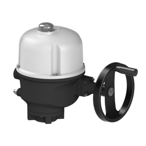
English 4 EMERGENCY HANDWHEEL OPERATION AQ actuators feature a handwheel for emergency operation. To avoid potentially harmful turning protruding parts during electrical operation, AQ handwheels feature a foldable handle: you can fold it during electrical operation and unfold it if you need to operate the actuator manually. -
Page 7: Position Feedback Potentiometer (Option)
English What to check after wiring Once actuator wiring is completed, please check the following: 1. Make sure that power supply voltage matches information on the sticker on the side of the actuator. 2. Check that all connectors or cable glands are correctly tightened. - Page 8 English How to set the potentiometer circuit board You can set the zero of the potentiometer with the 0% position screw. Use a flat blade screwdriver to turn this screw. 1. Drive the actuator to the CLOSED position. 2. Untighten the positioner pinion blocking screw. 3.
-
Page 9: Tam Position Transmitter (Option)
English TAM position transmitter (OPTION) The TAM transmitter delivers a 4 to 20 mA signal linearly proportional to the angular position of the valve. Electrical connections To connect TAM, refer to the wiring diagram supplied. Filtered or stabilized power supply should be provided within the 12 to 32 VDC range. - Page 10 English How to set TAM 1. Connect a milli-amp meter on terminal block. 2. Always start by adjusting the 4mA. 3. Drive actuator to the position corresponding to the 4 mA (CLOSED position). 4. Untighten the potentiometer pinion blocking screw. Adjust the potentiometer shaft so that the output current reaches a minimum value.
-
Page 11: Travel Limit Settings
English 5.4 Heating element Each actuator includes a heating resistor. As soon as the actuator is installed in the field, it is recommended to power the resistor to prevent condensation. • Immediately put the cover back in place after start-up while ensuring its seal is clean. -
Page 12: Cams And Mechanical Stops Setting
English How to adjust a single cam Take care that cams get to the lever according to its inclination direction, otherwise you could damage the switch. At the desired position of the actuator output: 1) Turn the setting screw of corresponding with a flat blade or a Phillips screwdriver. - Page 13 English How to adjust cams and mechanical stops for both directions One turn of the adjustment screw = 4° angle variation at the actuator output. Clockwise mechanical stop setting 1. Untighten the nut corresponding to clockwise mechanical stop and turn the mechanical stop 2 turns back. 2.
-
Page 14: Torque Limiting Device (Aq25 / 30 / 50 Only)
English 7 TORQUE LIMITING DEVICE (AQ25 / 30 / 50 only) The actuator is protected by a torque limiting device in case of over- torque. If the actuator stops in a position which is not the one desired, please check if actuator did not reach mechanical stops or that valve has no stiff point. - Page 15 SEOUL inquiry.russia@bernardcontrols.com inquiry.korea@bernardcontrols.com Tel. +33 (0)1 34 07 71 00 Tel. +82 2 553 6957 SPAIN SINGAPORE BERNARD CONTROLS SPAIN BERNARD CONTROLS SINGAPORE MADRID SINGAPORE inquiry.spain@bernardcontrols.com inquiry.singapore@bernardcontrols.com Tel. +34 91 30 41 139 Tel. +65 65 654 227 www.bernardcontrols.com www.bsa-armaturen.de...
Need help?
Do you have a question about the BERNARD CONTROLS AQ SWITCH Series and is the answer not in the manual?
Questions and answers