Table of Contents
Advertisement
Quick Links
Advertisement
Table of Contents

Related Manuals for Channel Safety Systems AlarmSense 2 ZONE

Summary of Contents for Channel Safety Systems AlarmSense 2 ZONE
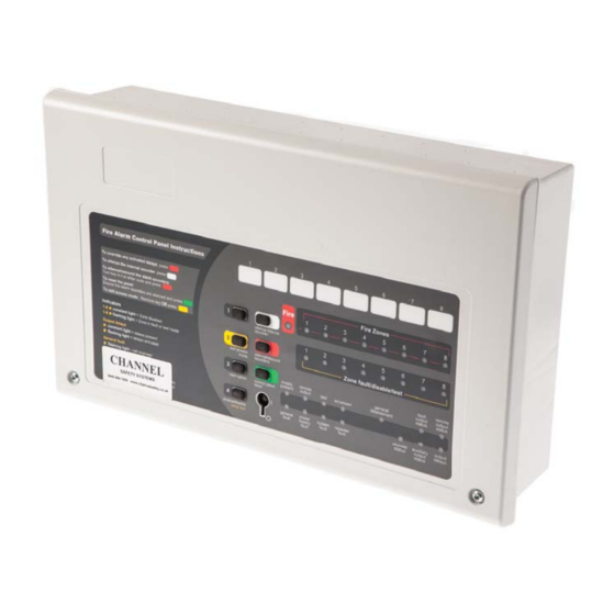
- Page 1 AlarmSense 2/4/8 ZONE CONVENTIONAL FIRE ALARM CONTROL PANEL CHANNEL SAFETY SYSTEMS t: 0845 884 7000 Petersfi eld Business Park f: 0845 884 6000 Bedford Road Petersfi eld Hampshire e: sales@channelsafety.co.uk GU32 3QA w: www.channelsafety.co.uk 2/4/8 ZONE CONVENTIONAL FIRE ALARM CONTROL PANEL...
-
Page 2: Table Of Contents
Contents Safety ..........................3 Important information regarding the safe use of this fi re alarm pane Key Features ........................3 Lists the diff erent features available on the range of conventional fi re alarm panels Fire Alarm Systems - An Overview ...................4 How fi re alarm systems operate and a general overview of their key features User Responsibilities... - Page 3 System Set-Up Data Chart ....................13 Details of how the system has been set-up Fire Alarm Log Book ......................14 A place for you to record details of events such as fi res, false alarms, call outs, etc. Certifi cate of Installation .........................19 Certifi cate of Commissioning ......................20...
-
Page 4: Safety
SAFETY The fi re alarm panel is safe to operate provided it has been installed in compliance with the manufacturer’s instructions and used in accordance with this user manual. Do not operate the fi re alarm panel with its enclosure open. There is no need to open the enclosure except to carry out com- missioning, maintenance and remedial work. -
Page 5: Fire Alarm Systems - An Overview
FIRE ALARM SYSTEMS – AN OVERVIEW The primary purpose of a fi re alarm system is to provide an early warning of a fi re so that people and animals can be evacu- ated and action taken to stop the fi re as soon as possible - all according to a predetermined plan. Alarms may be raised automatically by smoke or heat detectors, or manually by a person operating a manual call point. -
Page 6: User Responsibilities
USER RESPONSIBILITIES BS5839-1 is the British Standard code of practice for the design, installation, commissioning and maintenance of fi re detection and fi re alarm systems for buildings. Section 7 of the standard (User Responsibilities) states that a named responsible person should be appointed to supervise all matters pertaining to the fi re alarm system {clause 47.2a}. -
Page 7: Panel Layout/Accessing The Controls
PANEL LAYOUT/ACCESSING THE CONTROLS The fi re alarm panel allows both keyswitch and keypad entry methods for entering access level two. Note: Repeater Fault and Output Delays lights are not on the CFP Economy Panel. Two levels of control are available to user(s) of this fi re alarm panel; General User and Authorised User. 1. -
Page 8: What The Indicator Lights Mean
What the indicator lights mean The table below summarises the various indicators available on the fi re alarm panel and what they mean in their various states. The fi nal column highlights the pages(s) you should turn to for further information. LIGHT STATUS OF LIGHT WHAT THIS MEANS... -
Page 9: Fire Conditions
FIRE CONDITIONS Fire Zone Lights General Fire Light Fire Zones Fire When the fi re alarm panel receives an alarm trigger from a detector or manual call point located in a zone that is not already in a fi re state, it will: •... -
Page 10: Fault Conditions
FAULT CONDITIONS When a fault occurs on a critical part of the fi re alarm system, the panel responds by activating its internal sounder and il- luminating the General Fault light and any other Fault light(s) relating to the fault. The panel’s fault output will also activate (provided it hasn’t been disabled). -
Page 11: Disablements
DISABLEMENTS Certain fi re alarm panel functions can be temporarily disabled (i.e. switched off ) to suit certain conditions. For example, if there is a risk of a false alarm in a zone, e.g. from vehicle exhaust smoke in a loading bay, it is possible for the user to disable that zone during the risk period and enable it again afterwards. - Page 12 Notes about disablements (a) The option of disabling or enabling zones 3 & 4 and zones 5, 6, 7 & 8 is only available if these zones are fi tted. If they are not fi tted, the selection process will skip to the next available option. (b) The option of disabling or enabling output delays is only available if delays have been programmed into the fi re alarm panel by the installation engineer.
-
Page 13: Notes On Delays
NOTES ON DELAYS What is a delay? A delay can be programmed into the fi re alarm panel to postpone the activation of the alarm sounders and other outputs for a predetermined length of time. The delay period gives a responsible person time to investigate the cause of an alarm, usually in areas which are prone to false alarm (such as vehicle exhaust smoke in a loading bay) before the building is evacuated. -
Page 14: System Set-Up Data Chart
SYSTEM SET-UP DATA CHART Important: This page should be carefully completed by an authorised engineer prior to system hand-over. THE INFORMATION ABOVE WAS COMPLETED BY (name) _______________________________ OF (company) _________________________________________ ON (date) __________________ (*) NOTES ON COINCIDENCE: The following applies to all pairs of zones which are set up for coincidence. There must be alarms on both zones (i.e. -
Page 15: Fire Alarm Log Book
FIRE ALARM LOG BOOK It is recommended that this log book be maintained by a responsible person, who should ensure that every entry is properly recorded. In the UK, this is necessary to satisfy the recommendations of BS5839-1, compliance with which may be a require- ment of legislation. - Page 16 Details of tests (including fi re drills), actual fi re alarms, disablements or enablements and faults should be recorded here. False alarms and maintenance work should also be recorded on page 18 2/4/8 ZONE CONVENTIONAL FIRE ALARM CONTROL PANEL | 16...
- Page 17 2/4/8 ZONE CONVENTIONAL FIRE ALARM CONTROL PANEL | 17...
- Page 18 2/4/8 ZONE CONVENTIONAL FIRE ALARM CONTROL PANEL | 18...
- Page 19 False alarms Maintenance work 2/4/8 ZONE CONVENTIONAL FIRE ALARM CONTROL PANEL | 19...
-
Page 20: Certifi Cate Of Installation
BS5839-1 recommends that certifi cates be issued for all aspects of the fi re alarm system including design, installation, commissioning, acceptance, verifi cation (optional) and maintenance. Therefore, before this user manual is handed over, the following installation certifi cate and commissioning certifi cate (overleaf ) should be completed as appropriate by the relevant installation/commissioning engineer(s). -
Page 21: Certifi Cate Of Commissioning
BS5839-1 recommends that certifi cates be issued for all aspects of the fi re alarm system including design, installation, commissioning, acceptance, verifi cation (optional) and maintenance. Therefore, before this user manual is handed over, the following commissioning certifi cate and the installation certifi cate (overleaf ) should be completed as appropriate by the relevant installation/commissioning engineer(s). - Page 22 CHANNEL SAFETY SYSTEMS t: 0845 884 7000 Petersfi eld Business Park f: 0845 884 6000 Bedford Road Petersfi eld Hampshire e: sales@channelsafety.co.uk GU32 3QA w: www.channelsafety.co.uk 2/4/8 ZONE CONVENTIONAL FIRE ALARM CONTROL PANEL...
Need help?
Do you have a question about the AlarmSense 2 ZONE and is the answer not in the manual?
Questions and answers