Table of Contents

Related Manuals for National Instruments CVS-1459RT


Summary of Contents for National Instruments CVS-1459RT
- Page 1 National Instruments CVS-1459RT Manual Get Pricing & Availability at ApexWaves.com Call Today: 1-800-915-6216 Email: sales@apexwaves.com https://www.apexwaves.com/modular-systems/national-instruments/cvs-1450-series/CVS-1459RT...
- Page 2 NI Vision NI CVS-1459RT User Manual Compact Vision System with USB3 Vision and Reconfigurable I/O NI CVS-1459RT User Manual September 2014 374248A-01...
- Page 3 11500 North Mopac Expressway Austin, Texas 78759-3504 USA Tel: 512 683 0100 For further support information, refer to the NI Services appendix. To comment on National Instruments documentation, refer to the National Instruments Web site at ni.com/info enter the Info Code feedback...
- Page 4 National Instruments Corporation. National Instruments respects the intellectual property of others, and we ask our users to do the same. NI software is protected by copyright and other intellectual property laws. Where NI software may be used to reproduce software or other materials belonging to others, you may use NI software only to reproduce materials that you may reproduce in accordance with the terms of any applicable license or other legal restriction.
- Page 5 ™ The ExpressCard word mark and logos are owned by PCMCIA and any use of such marks by National Instruments is under license. The mark LabWindows is used under a license from Microsoft Corporation. Windows is a registered trademark of Microsoft Corporation in the United States and other countries.
- Page 6 Operation of this hardware in a residential area is likely to cause harmful interference. Users are required to correct the interference at their own expense or cease operation of the hardware. Changes or modifications not expressly approved by National Instruments could void the user’s right to operate the hardware under the local regulatory rules.
-
Page 7: Table Of Contents
Resources for NI LabVIEW, NI Vision Development Module, and NI Vision Acquisition Software Users ..............x Chapter 1 NI CVS-1459RT Overview About the NI CVS-1459RT ....................1-1 Hardware Overview......................1-1 Software Overview ......................1-2 NI Vision Builder for Automated Inspection ............1-3 LabVIEW........................ - Page 8 Restoring the NI CVS-1459RT to Factory Default Condition ......... 5-6 Appendix A Troubleshooting Software Configuration Problems ..................A-1 The NI CVS-1459RT Does Not Appear in MAX or in Vision Builder AI ....A-1 No Software is Installed.................... A-2 No Camera Found..................... A-2 Hardware Problems......................A-3 Cannot Drive Isolated Outputs .................
-
Page 9: About This Manual
NI CVS-1459RT Specifications—Contains detailed specifications for the NI CVS-1459RT. • NI CVS-1459RT Getting Started Guide—Explains how to install and configure the software necessary to use the NI CVS-1459RT, and how to get started using the NI CVS-1459RT hardware. • NI CVS I/O Accessory User Manual—Contains installation and operation instructions for the CVS I/O Accessory. -
Page 10: Resources For Ni Vision Builder Ai Users
MAX toolbar. Specific information about using MAX with NI Vision hardware is available by selecting Help»Help Topics»NI Vision»NI-IMAQdx. National Instruments Example Finder—LabVIEW contains an extensive library of VIs and example programs. To access the NI Example Finder, open LabVIEW and select Help»Find Examples. -
Page 11: Ni Cvs-1459Rt Overview
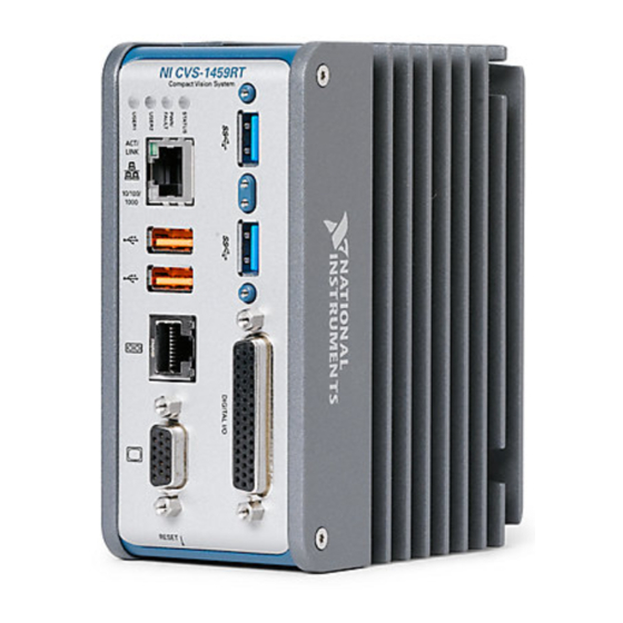
Hardware Overview The NI CVS-1459RT front panel consists of a VGA connector, RJ50 serial port, two USB 2.0 ports, a 10/100/1000 Ethernet connector, and two USB3 Vision ports. The NI CVS-1459RT front panel also includes LEDs for communicating system status and a 44-pin Digital I/O port. -
Page 12: Software Overview
Module 2014 or later; and NI-IMAQdx 14.0 or later driver software, included with NI Vision Acquisition Software August 2014 The NI CVS-1459RT has a user-reconfigurable FPGA that allows the I/O to be configured for particular applications. Different configurations are referred to as hardware personalities, and are defined by bitfiles. -
Page 13: Ni Vision Builder For Automated Inspection
The LabVIEW Real-Time Module combines LabVIEW graphical programming with the power of real-time (RT) hardware, such as the NI CVS-1459RT, enabling you to build deterministic, real-time systems. You develop VIs in LabVIEW and embed the VIs on RT targets. For more information about the LabVIEW Real-Time Module, refer to the LabVIEW Help. -
Page 14: Ni Vision Acquisition Software
NI Vision for LabVIEW Help. NI Vision Acquisition Software The NI CVS-1459RT ships with the latest version of NI Vision Acquisition Software, which contains all of the drivers in the NI Vision product line. With NI Vision Acquisition Software, you can quickly and easily start your applications without having to program the device at the register level. -
Page 15: Led Indicators And The Reset Button
This chapter provides information about the location and functionality of the LED indicators and the RESET button on the NI CVS-1459RT. LED Indicators Figure 2-1 shows the LEDs on the NI CVS-1459RT. Figure 2-1. LED Indicators NI CVS-1459RT Compact Vision System RESET ©... -
Page 16: Status Led
2 blinks There is no software installed, which is the out-of-box state, or the NI CVS-1459RT has detected an error in its software. The device has automatically started up into safe mode. This usually occurs when an attempt to upgrade the software is interrupted or if system files are deleted from the NI CVS-1459RT. -
Page 17: Pwr/Fault Led
Ethernet LEDs Figure 2-2 shows the LEDs for the primary Gigabit Ethernet network port. The primary network port provides a connection between the NI CVS-1459RT and the development computer. Figure 2-2. LEDs for the Primary Gigabit Ethernet Network Port Activity/Link LED Speed LED Refer to Table 2-3 for information on the Ethernet LED indications. -
Page 18: Using The Reset Button
Pressing the RESET button resets the processor in the same manner as cycling power. You can also use the RESET button to troubleshoot network connectivity: Hold the RESET button for 5 seconds, and then release it to boot the NI CVS-1459RT into safe mode. -
Page 19: Safe Mode
TCP/IP settings are invalid. When the NI CVS-1459RT is in the IP reset state, the IP address of the network port resets to DHCP or a link-local address. You can then set up a new network configuration for the NI CVS-1459RT from a development machine on the same subnet, or you can connect the NI CVS-1459RT directly to the development computer. -
Page 20: Connector Pinouts
Connector Pinouts This chapter describes the connectors on the NI CVS-1459RT and includes pinouts and signal descriptions for each connector. Table 3-1 summarizes the functions of the connectors and features on the NI CVS-1459RT. Table 3-1. Connector Overview Connector Function... - Page 21 Chapter 3 Connector Pinouts Figure 3-1 shows the locations of the connectors. Figure 3-1. NI CVS-1459RT Front Panel Connectors NI CVS-1459RT Compact Vision System RESET 1 VGA Connector 4 RJ45 Gigabit Ethernet Network Port 2 RJ50 Serial Port 5 USB3 Vision Ports 3 USB 2.0 Ports...
-
Page 22: Chassis Grounding Screw
NI CVS-1459RT User Manual Chassis Grounding Screw Use the grounding screw on the NI CVS-1459RT, shown in Figure 3-2, to connect the chassis to earth ground. An earth ground connection is optional. An earth ground connection does not connect C or C to earth ground. -
Page 23: Power Input Connectors
Chapter 3 Connector Pinouts Power Input Connectors The NI CVS-1459RT uses two power supplies to power the system and to power the isolated outputs. Figure 3-3 shows the power connectors. Figure 3-3. Power Connectors 1 System Power Connector 2 Isolated Outputs Power Connector Table 3-2 describes the terminals on the power connectors. -
Page 24: Ethernet Port
NI CVS-1459RT User Manual Ethernet Port The Ethernet port on the NI CVS-1459RT provides a connection between the NI CVS-1459RT and the development computer, either directly or through a network. The NI CVS-1459RT automatically detects the speed of the connection and configures itself accordingly. -
Page 25: Usb 2.0 Ports
USB Data + Ground RS-485/422/232 Serial Port The NI CVS-1459RT has a single serial port that can operate in either RS-485/422 mode or RS-232 mode. Set the serial port mode in the BIOS. Refer to the Serial Port Configuration Submenu... -
Page 26: Vga Port
Unused VGA Port Use the VGA port to connect a monitor to the NI CVS-1459RT. Use any standard 15-pin VGA cable to access the VGA port. The VGA port has a maximum resolution of 1920 x 1200 at 60 Hz. - Page 27 Chapter 3 Connector Pinouts Figure 3-7. VGA Port Pin Locations The following table lists the VGA signals. Table 3-6. VGA Port Pin Descriptions Signal Name Signal Description Red analog video signal GREEN Green analog video signal BLUE Blue analog video signal RESERVED Reserved Ground reference...
-
Page 28: Usb3 Vision Ports
NI CVS-1459RT User Manual USB3 Vision Ports The NI CVS-1459RT provides two standard A USB 3.0 ports to acquire images from two USB3 Vision cameras simultaneously. The USB ports also support common USB mass-storage devices such as USB flash drives, USB-to-IDE adapters, keyboards, and mice. -
Page 29: Digital I/O
Connector Pinouts Digital I/O The 44-pin Digital I/O port on the NI CVS-1459RT offers 8 isolated inputs, 8 isolated outputs, 2 bidirectional differential inputs (RS-422) or single-ended input lines that can be used with a quadrature encoder, and 8 bidirectional TTL lines. The Digital I/O port can be connected to any appropriate shielded device or connector block using a shielded cable. - Page 30 NI CVS-1459RT User Manual Table 3-8. Pin Location and Definition for the NI CVS-1459RT Digital I/O (Continued) Pin Location Number Signal Description TTL 6 Bidirectional TTL I/O TTL 7 Bidirectional TTL I/O Digital ground reference for TTL and differential I/O...
-
Page 31: Wiring An Isolated Input
You can wire an isolated input to a sourcing output device, as shown in the Figure 3-9. Do not apply a voltage greater than 24 VDC to the isolated inputs. Voltage Caution greater than 24 VDC may damage the NI CVS-1459RT. Figure 3-9. Connecting an Isolated Input to a Sourcing Output Device Power Supply... -
Page 32: Connecting To Differential I/O
NI CVS-1459RT User Manual Connecting to Differential I/O The NI CVS-1459RT accepts differential (RS-422) line driver inputs. Each of the 2 differential I/O can be configured as an output. Use shielded cables for all applications. Unshielded cables are more susceptible to noise and can corrupt signals. Figure 3-11 shows the differential input/quadrature encoder input circuit. - Page 33 Chapter 3 Connector Pinouts Figure 3-12. Connecting Differential Line Drivers Encoder NI CVS-1459RT Diff In 0+ Phase A Twisted Pair – Diff In 0– Phase A Diff In 1+ Phase B Twisted Pair – Diff In 1– Phase B Figure 3-13. Connecting Single-Ended Line Drivers...
-
Page 34: Ttl I/O
NI CVS-1459RT User Manual TTL I/O Figure 3-14 shows the circuit for a bidirectional TTL I/O. Figure 3-14. TTL Input/Output Circuit 10 kΩ TTL_OUT(0) 100 Ω TTL_OE(0) TTL I/O TTL_IN(0) © National Instruments | 3-15... -
Page 35: Connecting Multiple Ni Cvs-1459Rt Devices
IP address, configure the NI CVS-1459RT, download inspection tasks, and remotely monitor an ongoing inspection. You can connect multiple NI CVS-1459RT devices to the same network, as shown in Figure 4-1. Figure 4-1. Multiple NI CVS-1459RT Devices Connected to the Same Network To connect multiple NI CVS-1459RT devices to the same network, each device must have a unique IP address. - Page 36 VGA connector on the NI CVS-1459RT, as shown in Figure 4-2. Figure 4-2. NI CVS-1459RT Connected to a Monitor At any time, you can reconnect the host machine to the NI CVS-1459RT device and remotely monitor progress. 4-2 | ni.com...
-
Page 37: Bios Configuration And System Recovery
BIOS Configuration and System Recovery You can change the configuration settings for the NI CVS-1459RT in the BIOS setup. The BIOS is the low-level interface between the hardware and PC software that configures and tests your hardware when you boot the system. The BIOS setup program includes menus for configuring settings and enabling features. -
Page 38: Main Menu
Chapter 5 BIOS Configuration and System Recovery Menu items listed in blue are changeable; menu items in gray are not changeable. A blue triangle next to a menu item indicates that the menu item contains a submenu. The following sections describe the entries available in each BIOS menu. Main Menu The most commonly accessed and modified BIOS settings are in the Main setup menu. -
Page 39: Serial Port Configuration Submenu
Auto, Floppy, Forced FDD, Hard Disk, and CD-ROM. The default is Auto. Boot Menu This screen displays the boot order of devices associated with the NI CVS-1459RT. The BIOS proceeds down the Boot priority order list in search of a bootable device. Devices under the Excluded from boot order list will not be used for booting. -
Page 40: Boot Settings Configuration Submenu
Chapter 5 BIOS Configuration and System Recovery • PXE Network Boot—This setting specifies whether or not the PXE network boot agent is enabled. When this setting is enabled, the Intel Boot Agent is displayed in the Boot Option Priorities menu, allowing you to boot from a PXE server on the local subnet. Note that the Intel Boot Agent device names are preceded by IBA GE Slot in the Boot Option Priorities menu. -
Page 41: Save & Exit Menu
NI CVS-1459RT User Manual Hard Drive BBS Priorities Submenu • Boot Option #1, Boot Option #2, Boot Option #3—These settings specify the boot priority of hard drive devices. The highest priority device is displayed on the main Boot Option Priorities list. Optionally, each device can also be Disabled if the device should never be used as a boot device. -
Page 42: Restoring The Ni Cvs-1459Rt To Factory Default Condition
Defaults option in the Save & Exit Menu of the BIOS to restore the BIOS settings. Start the NI CVS-1459RT in safe mode. To start in safe mode, press the RESET button for more than 5 seconds. Launch MAX. In the MAX configuration tree, expand Remote Systems. -
Page 43: Appendix A Troubleshooting
Possible causes and solutions: • The NI CVS-1459RT may not be powered. Verify that there is system power to the device and that both the NI CVS-1459RT and the development computer are properly connected to the network. The PWR/FAULT LED should be lit green and the ACTIVITY/LINK LED on the primary network port should flash green when refreshing the list of devices in MAX or Vision Builder AI. -
Page 44: No Software Is Installed
You may be experiencing firewall issues. If you are having difficulty detecting the system and setting up the NI CVS-1459RT on your network, you must configure the firewall to open the TCP/UDP ports used by the NI CVS-1459RT and the host machine. Refer to the following table for more information about TCP/UDP ports. -
Page 45: Hardware Problems
NI CVS-1459RT. If the BIOS setting Restore After Power Loss is set to Stay Off, the NI CVS-1459RT may be powered, but turned off. Press the RESET button to power on the device. -
Page 46: Appendix B Mounting Information
This appendix provides information for creating a custom mount for the NI CVS-1459RT. If you do not want to create a custom mount, a panel and DIN rail mount kit for the NI CVS-1459RT is available from National Instruments (part number 781740-01). - Page 47 Appendix B Mounting Information Figure B-1. Front View of the NI CVS-1459RT with Dimensions in inches [millimeters] B-2 | ni.com...
- Page 48 Figure B-2. Back View of the NI CVS-1459RT with Dimensions in inches [millimeters] You can ground the NI CVS-1459RT to your mount by connecting a Note grounding wire to the chassis grounding screw on the NI CVS-1459RT. Refer to the Chassis Grounding Screw section of Chapter 3,...
- Page 49 Appendix B Mounting Information Figure B-3. Side View of the NI CVS-1459RT with Dimensions .150 in. (3.80 mm) 4.121 in. (104.67 mm) 5.133 in. (130.38 mm) 4.270 in. (108.47 mm) B-4 | ni.com...
-
Page 50: Clearance Requirements
The NI CVS-1459RT installation must meet the following space and cabling clearance requirements for optimum cooling: • Allow 76.2 mm (3.0 in.) on the top and bottom of the NI CVS-1459RT for air circulation. • Allow 50.8 mm (2.0 in.) on the sides of the NI CVS-1459RT for air circulation. - Page 51 Appendix B Mounting Information Refer to Figure B-5 for the clearance requirements for the NI CVS-1459RT. Figure B-5. Clearance Requirements for the NI CVS-1459RT 76.2 mm (3.00 in.) NI CVS-1459RT Compact Vision System 50.8 mm 50.8 mm (2.00 in.) (2.00 in.) RESET 76.2 mm...
-
Page 52: Ni Services
NI Services National Instruments provides global services and support as part of our commitment to your success. Take advantage of product services in addition to training and certification programs that meet your needs during each phase of the application life cycle; from planning and development through deployment and ongoing maintenance. - Page 53 • Training and Certification—The NI training and certification program is the most effective way to increase application development proficiency and productivity. Visit for more information. ni.com/training – The Skills Guide assists you in identifying the proficiency requirements of your current application and gives you options for obtaining those skills consistent with your time and budget constraints and personal learning preferences.
Need help?
Do you have a question about the CVS-1459RT and is the answer not in the manual?
Questions and answers