
Related Manuals for QEI 6QBI

Summary of Contents for QEI 6QBI
- Page 1 DIO-9100 USER’S GUIDE UG-1062 UG-1091 6QBI QUICS Board Interface User’s Guide April 2021...
- Page 2 The information in this document has been carefully checked and is believed to be accurate. However, no responsibility is assumed or implied for inaccuracies. Furthermore, QEI, LLC reserves the right to make changes to any products herein described to improve reliability, function or design. QEI, LLC does not assume liability arising out of the application or use of any product or circuit described herein;...
- Page 3 6QBI User’s Guide UG-1091 Revisions Revision Description Date Initial Release Dec 6 2018 Changes due to firmware Dec 19 2018 revisions. Changes due to firmware Jan 18 2019 revisions. Changes due to firmware Jun 19 2019 revisions. Changes due to firmware...
-
Page 4: Table Of Contents
6QBI User’s Guide UG-1091 Contents 1 Description ................1 2 Specifications ................2 3 Input Power Connections ............4 4 6SIP1 Status Panel Interface ...........5 General ................5 6SIP1 Status Connector J6 Pinout ........6 5 6COP1 Control Panel Interface ..........7 General ................7 6COP1 Control Connector (J5) Pinout ......... - Page 5 6QBI User’s Guide UG-1091 15.3.1 Analog Monitoring ..........24 15.3.2 Status Monitoring ..........24 15.3.3 Accumulator Monitoring ........24 15.3.4 Control Operation ..........24 15.4 Help for Test Panel Commands ......... 24 15.5 Reading Analog Values (RA) ..........26 15.6 Reading Status Values (RS) ..........26 15.7 Reading Accumulator Values (RC) ........
-
Page 6: Description
I/O panel per RTU, along with all the same functionality for the panels. With the QUICS-3000 series panels the number of status points is limited to 320. For analogs and control points, the 6QBI supports up to the maximum allowable via a 6PIB1. -
Page 7: Specifications
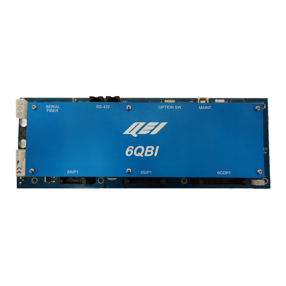
6QBI User’s Guide UG-1091 RS-422 OPTION SW. MAINT. 6AIP1 6SIP1 6COP1 Specifications General Description Main Microcontroller Microchip 16-Bit 128KB Flash 96 MHz Communications Ports Port 1: Interface Isolated RS-422 (Main Port #1) Bit Rate 115.2Kbps Protocol Asynchronous Byte Oriented Connector... - Page 8 6QBI User’s Guide UG-1091 Current 100 mA max. Safety One relay operation at a time. Connector 34-pin IDC header. (J6) Status Point Interface Panel type 6SIP1 or 6PIB1 Bit Width 16 bits Addressability Sixteen 6SIP1 Panels x 16 pts/panel = 256 points or Twenty...
-
Page 9: Input Power Connections
6QBI User’s Guide UG-1091 3 Input Power Connections The 6QBI accepts +12Vdc input nominal, maximum +16Vdc. Input power connections are made at 3-pin connector J8. J8 PIN# Name Description +DC Input Connect a +12Vdc Power Supply here. Common Power supply common connection here. -
Page 10: 6Sip1 Status Panel Interface
6QBI User’s Guide UG-1091 4 6SIP1 Status Panel Interface General The Status Panel Interface (J6) provides the means for the system to sample digital input data points. These digital points can be configured in various ways, for example: • Individual Status Points (on/off indications) •... -
Page 11: 6Sip1 Status Connector J6 Pinout
6QBI User’s Guide UG-1091 6SIP1 Status Connector J6 Pinout J6 PIN# Name Description +12V +12V Power out to 6SIP1 Panels. SIP ACK 6SIP1 Panel Acknowledge Input. Power output common. Power output common. PSEL BIT3 Panel Select Bit 3. PSEL BIT1 Panel Select Bit 1. -
Page 12: 6Cop1 Control Panel Interface
6QBI User’s Guide UG-1091 5 6COP1 Control Panel Interface General The Control Panel Interface (J5) provides the means for the system to momentarily energize external relays (control output points) in response to control commands received from the "client", or locally generated from internal processes. -
Page 13: 6Cop1 Control Connector (J5) Pinout
6QBI User’s Guide UG-1091 6COP1 Control Connector (J5) Pinout J5 PIN# Name Description No Connect. No Connect. 3 thru 10 TRIP 0-7 Trip Row Lines 0 thru 7. 11 thru 18 CLOSE 0-7 Close Row Lines 0 thru 7. 19 thru 34 COLUMN 0-15 Column Lines 0 thru 15. -
Page 14: 6Aip1 Analog Panel Interface
6QBI User’s Guide UG-1091 6 6AIP1 Analog Panel Interface General The Analog Panel Interface (J7) samples differential analog input signals that are wired to the 6AIP1 or 6AMP Analog Input Panels, at any given time one of up to eight 6AIP1s and one of the sixteen input points in each pane is selected. The Analog Panel Interface continuously samples in this manner for a total of 128 analog inputs. -
Page 15: 6Aip1 Analog Connector (J7) Pinout
6QBI User’s Guide UG-1091 6AIP1 Analog Connector (J7) Pinout J7 PIN# Name Description +ANA IN + Analog Input +A15 6AIP1 Power +15Vdc. 3,5,7 PNL SEL X Power Common -A15 6AIP1 Power -15Vdc. 6 &8 ACOM Power Common 7,9,11,13 PT SEL X Panel Point Select &... -
Page 16: Communications Ports
RTU. There are two RS-422 ports on the 6QBI. These ports may be used one at a time, or simultaneously for redundant communications with the 6QBI by two RTUs. Both of the 6QBI RS-422 ports are isolated (shared isolation) and transient protected. -
Page 17: Serial Fiber Port (Optional)
J16 enables it for Port 2 (J13). Serial Fiber Port (Optional) The optional Serial Fiber Port (TX/RX) allows for 6QBI communications with the ePAQ-9410 or ePAQ-942x via serial fiber. Connections are made via ST fiber connectors using multimode POF fiber. It may be necessary to remove the 6QBI front cover to reach the fiber connections. - Page 18 6QBI User’s Guide UG-1091 SERIAL RS-422 OPTION SW. MAINT. FIBER 6AIP1 6SIP1 6COP1 • Copyright © 2021 QEI Communications Ports...
-
Page 19: Usb Maintenance Port (J5)
USB-B to USB-A cable (not supplied). This port is compatible with terminal programs such as TeraTerm, PuTTY, and HyperTerm and may require installation of the 6QBI USB driver depending on Windows version. Any baud rate will work with the 6QBI. MAINT. -
Page 20: Dip Switches
6QBI User’s Guide UG-1091 8 Dip Switches Option DIP Switches (SW1) SW1 is a 4-position dip switch bank. During normal RS-422 communications, all four DIP switch positions are OFF (UP). The function of each switch is as follows: DIP Switch #... -
Page 21: Watchdog Disable Switch (Sw1 Position 6)
6QBI User’s Guide UG-1091 Watchdog Disable Switch (SW1 Position 6) DIP switch SW1 position 6. Turning on this DIP switch disables the watchdog circuit. This switch is a factory setting. When the SW1 switch is OFF (UP), the watchdog circuit is enabled (factory setting) and LED D1 is off. -
Page 22: Led Indications
The 6QBI includes various red and green LED indications. Many of the LEDs are visible along the edges of the 6QBI. Other LEDs are located on the PCB, behind the front cover (see Location column in the table below), and cannot easily be viewed without removing the front panel. -
Page 23: Earth Grounding
Failure to do so will render the transient protection circuits on the 6QBI RS-422 ports inoperative, and may result in damage to the board. The J20 grounding tab is also located near the top left swage-on mounting hole. -
Page 24: Installation
12 Installation 12.1 General The 6QBI takes up less than half the space of a 6CPP6 panel, and can generally be mounted wherever a 6CPP6 was mounted in the RTU cabinet. The 6QBI and 6CPP6 swage-on standoffs located along the Analog/Status/Control ribbon cable board edge are in the same locations, and accept the same mounting hardware (6-32 screws). - Page 25 6QBI User’s Guide UG-1091 PORT 20 PORT 21 PORT 22 PORT 23 PORT 24 PORT 25 PORT 26 PORT 27 PORT 28 PORT 29 PORT 30 PORT 31 PORT 32 PORT 33 PORT 34 PORT 35 (J13A) (J13B) (J13C) (J13D)
-
Page 26: Ordering Information
Products. It serves as a communications interface between the ePAQ-9410/942x or MicroPAQ-940P and the QUICS III (6PIB1 Required) or QUICS IV I/O Cards. The 6QBI mounts in less than half the space of an existing 6CPP6 panel in any existing RTU cabinet. -
Page 27: Software
General The 6QBI communicates with either a MicroPAQ-940P or ePAQ-9410/942x. The 6QBI does not require software configuration, and no special 6QBI “Client” is required for either the MicroPAQ-940P or ePAQ-9410/ePAQ-942x, the 6QBI will appear to the gateway as its own local I/O. See the Addendum for more specific configuration information. -
Page 28: Test Panel (Maintenance)
The 6QBI appears as a serial Com: port under Windows. Open PC communications program and select the proper 6QBI serial port – it will appear under “connected device” window. Configure the port as 8 bit, 1 stop, no parity, no-flow, 6QBI will connect at any speed. -
Page 29: Functional Test Capability
15.3.1 Analog Monitoring The test panel may be used to display the value of any analog point within the 6QBI subsystem. The information displayed (unscaled raw value) will represent the digital value produced by the subsystem's analog-to-digital conversion of the analog input value. - Page 30 6QBI User’s Guide UG-1091 Read Accumulators RC <first> [last] Control Close CN <point> [delay] Control Trip CF <point> [delay] Print Port Traffic PRX <port> [option] [option] Print Code Version Read Dip Switches Set Time of Day TIME <hh:mm> <hh:mm.ss> Set Date of Day DATE <mm/dd/yyyy>...
-
Page 31: Reading Analog Values (Ra)
6QBI User’s Guide UG-1091 15.5 Reading Analog Values (RA) Analog points can be selected and displayed in real-time. You may use the panel address to simplify point entry. To enter the desired analog points, proceed as follows: Example read single point: RA 4 <enter>... -
Page 32: Relay Control
6QBI User’s Guide UG-1091 15.8 Relay Control CAUTION!! THE FOLLOWING PROCEDURE WILL ENERGIZE RELAYS CONNECTED TO CONTROL POINTS. MAKE CERTAIN THAT EITHER IT IS SAFE TO COMMAND THE POINT OR THAT THE FIELD DEVICE IS DISCONNECTED FROM THE RELAY. Two (2) relay commands can be entered by the Test Panel to operate control relays. -
Page 33: Communication Checks
Note that the value within [xxxx] is relative time stamp in milliseconds between messages. The tx[] time value will typically be same as rx[] value because the 6QBI processes message quickly. Also note that the max time between messages is 9999ms (9.999 seconds) and will roll over to zero (0). -
Page 34: Displaying The Software Version (Ver)
(+/- 5 Volts DC) a calibration value can be determined and save in the 6QBI internal Eprom memory. Setup: Install a 6QBI with the appropriate link and a single AIP or 6AMP (w/ 6PIB1) panel, address set to zero (0). - Page 35 Press ‘n’ to select -5Vdc input mode, make sure this voltage is applied to Point 0. Press ‘s’ to save the calibration values to Eprom. The 6QBI internal calibration memory can be reset to default (1.0) by pressing the ‘R’ key. The 6QBI will indicate during PRCAL <enter> ‘!’ to indicate “un-calibrated”...
Need help?
Do you have a question about the 6QBI and is the answer not in the manual?
Questions and answers