Advertisement
Quick Links
Installation, Operation and Maintenance Instructions
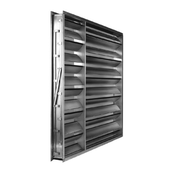
RGK Reglair Precision control dampers
Shipment
In principle, avoid all damage caused by external influ-
ences. Never lift dampers by the slats or the outer linkages.
Dampers with a maximum weight of 50 kg can be lifted
by the C-profile frame. With heavier dampers, use at least
four points at the corner angles as suspension points. Do
not use individual slats under any circumstances as foot-
holds during installation. Report any damage, e.g. defor-
mation of slats, dents, impacts or warping of the C-profile
frame etc. immediately to the supplier or manufacturer.
This may impair the proper functioning of the damper and
at best cause dangerous circumstances to occur.
ATEX: Under no circumstances may ATEX dampers be fitted
after a fall or impact with visible or concealed damage.
Installation
Mount the dampers warp-free, tension-free, on a flat sur-
face and without any angular errors in the damper frame.
When mounting, use the 4 corner holes provided as stand-
ard. With larger dampers, fit additional flange couplings
at spacings of 200–500 m m. This is the responsibility of
the planning engineer or fitter. When installation is com-
plete, check the angle of the damper frame. It must be
exactly 90°. Correct any deviations immediately. In addi-
tion check the free movement of the slats, linkage and
gear wheels. Avoid as far as possible any reduction in free-
dom of movement on customer premises when installing
insulation materials, installation ducts, auxiliary structures
etc. If this is not observed, it can lead to considerable dis-
LUCOMA AG, Weekendweg 5, CH-3646 Einigen, Switzerland
Tel: +41 33 655 00 44, Fax: +41 33 655 00 45, www.lucoma.com, info @ lucoma.com
Product designation
RGK-10..., RGK-15..., RGK-17..., RGK-30..., RGK-50..., RGK-51...
Technical specifications
Max. size W×H:
Max. slat length:
Max. air velocity:
Closing torque:
Closing torque with MS:
Closing direction:
Air flow direction:
Free cross section:
ATEX
RGK dampers are only approved in specific designs and with appropriate iden-
tification for Zones 1, 21 or 2, 22 according to Atex Directive 2014/34/EU.
If the fitter or operator changes the dampers in any way, the ATEX approval
becomes null and void. It is important to ensure that the damper and addition-
al equipment are installed in compliance with zoning requirements.
ruptions in operation, e.g. slats rub against the damper
frame, increased damper torque, damper fails to open or
close, reduced leak tightness, fatigue fractures on the
axles etc.
Only dampers which are equipped with collar bushings
can be fitted with vertical slats (also called standing slats).
In addition, make sure with this damper application that
additional bolts or reinforcements are affixed with damp-
ers larger than 1000 × 1 000 m m. The lower frame profile
on which the entire slat weight rests must also be supported
by the customer. Sagging can lead to damper damage
and plant outages.
On models with side seals (Di, DIN, CEN, S etc.) protect the
units from impurities of all kinds during the installation
phase. Drilling swarf and concrete chips can damage the
side seals. Before starting up the dampers, wipe the side
seals thoroughly until they are dry.
ATEX: All relevant national and international standards
and regulations for Ex zones must be observed. On damp-
ers with ATEX functionality in particular, the damper hous-
ing must be earthed using the earthing braids attached
by the manufacturer. No mechanical changes may be
made to the product. In addition do not attach any com-
ponents (motors, limit switches, etc.) to the damper if they
have not been analyzed for ignition risk by the appropriate
manufacturers or approved for ATEX zones.
It is prohibited to drill holes or fit bolts or screws in the in-
terior of the dampers. This could lead to damage or dis-
turb damper operation. If there is a risk at the factory that
7900 m m × 7 900 m m (subject to shipping)
100 m m slat max. 2000 m m,
150 m m slat max. 2500 m m
20 metres per second
M (Nm) = (0.23 × Q ) + ( B(m) × Q )
M (Nm) = (0.46 × Q ) + ( B(m) × Q )
M = closing torque in Nm, B = damper width,
Q = number of slats
clockwise as standard
freely selectable
> 60 % (more precise figures after calculation
by manufacturer)
Advertisement

Related Manuals for LUCOMA RGK-10 Series

Summary of Contents for LUCOMA RGK-10 Series
- Page 1 If this is not observed, it can lead to considerable dis- turb damper operation. If there is a risk at the factory that LUCOMA AG, Weekendweg 5, CH-3646 Einigen, Switzerland Tel: +41 33 655 00 44, Fax: +41 33 655 00 45, www.lucoma.com, info @ lucoma.com...
- Page 2 ATEX: All relevant national and international standards RGK models operate maintenance-free. and regulations for Ex zones must be observed. In particular, Only LUCOMA genuine spare parts may be used for all only drive motors, limit switches, sensors etc. with special repair and maintenance work.
Need help?
Do you have a question about the RGK-10 Series and is the answer not in the manual?
Questions and answers