Table of Contents
Advertisement
Quick Links
EOC Master CD7944N Product User Manual
---
Device Install Guide
Version:V1.0
Company Address: Room 601, Floor 6, Building F, Songbai Road 1008, Sunshine Community,Xili Street, Nanshan District, Shenzhen(518108)
Factory Address: Fl1, Bldg B, Wentao Industrial zone, Yingrenshiyongxin Village, Shiyan Street, Baoan district, Shenzhen, Guangdong, China (518055)
Tel: +86-755-26014509/4710/4711 Fax:+86-755-26014506
Website: www.cdatatec.com
Advertisement
Table of Contents

Summary of Contents for Data EOC Master CD7944N
- Page 1 EOC Master CD7944N Product User Manual Device Install Guide Version:V1.0 Company Address: Room 601, Floor 6, Building F, Songbai Road 1008, Sunshine Community,Xili Street, Nanshan District, Shenzhen(518108) Factory Address: Fl1, Bldg B, Wentao Industrial zone, Yingrenshiyongxin Village, Shiyan Street, Baoan district, Shenzhen, Guangdong, China (518055) Tel: +86-755-26014509/4710/4711 Fax:+86-755-26014506 Website: www.cdatatec.com...
-
Page 2: Table Of Contents
Contents 1 Introduction............................. 1 1.1 Product Description......................1 1.2 Networking Introduction...................... 1 2 Service Configuration........................2 2.1 Device Installation Instruction....................2 2.1.1 Typical Networking....................2 2.1.2 Device Installation Step.....................2 2.1.3 Preparations Before Installation................2 2.1.4 Network Device Installation..................3 2.1.4.1 EOC Master Installation................. 3 2.1.4.2 CD7944N Panel Interface and Indicators............ -
Page 3: Introduction
EOC series products have many advantages such as flexible deployment, high bandwidth, high security, good reliability, convenient management, and simple maintenance. EOC technology theory: EOC system uses coaxial lines to transmit data signals at below 65 MHz. When transmitting, the user data is modulated using GMSK or OFDM modulation technology, and then transmitted on the coaxial cable. -
Page 4: Service Configuration
2 Service Configuration 2.1 Device Installation Instruction The actual networking mainly includes EOC master CD7944N installation, EOC slave device installation, and EOC accessories installation. 2.1.1 Typical Networking Typical networking application is shown in Figure 1. 2.1.2 Device Installation Step Reference sequence: EOC Master installation → coaxial cable connection → EOC slave installation→verification... -
Page 5: Network Device Installation
2.1.4 Network Device Installation 2.1.4.1 EOC Master Installation The network equipment installation at the optical node mainly includes: EOC master CD7944N , installation accessories (hanging buckle, etc.). 2.1.4.2 CD7944N Panel Interface and Indicators 2.1.4.3 CD7944N Panel Definition EOC partial panel (Including two EOC modules) Interface Description Usage... - Page 6 Interface Description Usage 1*GPON port, FSAN G.984.2 standard, support backward Uplink connect MAN optical PON port compatibility with EPON network port SC/UPC single mode single fiber The optical signal received by 4*10/100/1000Mbps adaptive ports the ONU is converted into Full/half duplex mode LAN port Electrical signal...
-
Page 7: Requirements Before Construction
2.2 Requirements Before Construction 2.2.1 EOC Master Requirements Before Construction 2.2.1.1 EOC Master Installation Requirements The device should not be installed near large power transmission and transformation equipment, radio signal transmission towers and other facilities. The equipment should not be placed in a humid environment such as a basement. It is strictly prohibited to stack flammable, explosive, strong corrosive and other dangerous goods around the equipment. -
Page 8: Eoc Master Grounding Requirements
2.2.1.3 EOC Master Grounding Requirements Index Item Specifications When there is a ground bar in the installation environment of the device, which uses a yellow-green two-color protective ground cable to directly connect to the ground bar. If you need to make a protective ground cable on site, the cross-sectional area is not less than 6 ㎡, and the length should not exceed 3m. -
Page 9: Eoc Master Power Requirements
connected together by a 35 ㎡ yellow-green two-color protective grounding cable or directly welded together. The welding points should be anti-corrosive. 2.2.1.4 EOC Master Power Requirements Voltage: Support AC220V power supply or AC60V coaxial feed power, and allowable change range is + 10% ~ -10%. Frequency: 50Hz. -
Page 10: Construction Specifications
Power waveform: Sine wave distortion is not more than 3%. 2.3 Construction Specifications 2.3.1 EOC Master Installation The equipment installation position should meet the design requirements. In case of any changes, it must be approved by the design and construction unit and complete change procedures. -
Page 11: Cable Laying
2.3.3 Cable Laying The specifications, models, and quantities of cables should meet engineering design requirements. The cable must be a whole wire with a complete sheath. The cables should be straight and tidy., and avoid cross-entanglement. The remaining cable length should be uniform, At the same time,wiring locations for equipment expansion.should be reserved. -
Page 12: Installation Method
The identification of the label should indicate the name, number, and management IP address assignment of the equipment according to the design text. the CAT5, power line and coaxial cable should indicate the direction of the line. 2.4 Installation Method 2.4.1 Installation Preparation Tool preparation Universal tools: Marker, knife, special hexagon wrench, adjustable wrench, vise,... -
Page 13: Hanging Installation
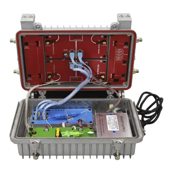
2.4.2 Hanging Installation Before hanging installation, it must be ensured that the strength of the equipment hanging place can meet the load bearing. 2.4.3 Opening EOC Master Flap Before connecting EOC Master cable, you need to loosen four hex screws on the flap with the special hex wrench, as shown in the figure below: Company Address: Room 601, Floor 6, Building F, Songbai Road 1008, Sunshine Community,Xili Street, Nanshan District, Shenzhen(518108) Factory Address: Fl1, Bldg B, Wentao Industrial zone, Yingrenshiyongxin Village, Shiyan Street, Baoan district, Shenzhen, Guangdong, China (518055) -
Page 14: Connect Eoc Master Cable Line
2.4.4 Connect EOC Master Cable Line The EOC Master provides 4 cable mixed output interfaces. As shown in the figure below, the user's coaxial cables that need to be covered are connected to the four cable ports on the EOC master, and the cable interfaces are tightened one by one to complete the user signal coverage. -
Page 15: Construction Self-Inspection
2.5 Construction Self-Inspection After the line transformation and equipment installation are completed, before the system is powered on, please check the installation equipment, components and materials, and the installation process referring to the construction specifications. After the system is powered on, you can install the EOC master at the user home. Check whether the EOC slave is registered and online normally, whether the service is normally opened, and whether the performance meets the expected requirements. -
Page 16: Eoc Master Login Method
2.6 EOC Master Login Method This equipment does not have out-band management port. By default, it only supports in-band management. There are two ways to login the device WEB interface. One is to access EOC master WEB from the front-end equipment(such as OLT, server, etc.) of the optical node. -
Page 17: From Eoc Master Front-End Equipment Access
2.6.2.2 From EOC Master Front-end Equipment Access The figure below is a networking diagram of accessing EOC master WEB from front-end equipment. According to the diagram, the PC is connected to the OLT uplink port, and configure the same network segment IP address as in-band management IP of EOC master to ensure that the PC can ping through EOC master. -
Page 18: Concluding Remarks
Concluding Remarks Thanks for using products of Shenzhen C-Data Technology Co. Ltd. Contact Information: Company Address: Room 601, Floor 6, Building F, Songbai Road 1008, Sunshine Community, Xili Street, Nanshan District, Shenzhen, China Factory Address: 1 floor, Building B, Wentao Industrial Park, Yingrenshi Community,...
Need help?
Do you have a question about the EOC Master CD7944N and is the answer not in the manual?
Questions and answers