Table of Contents

Summary of Contents for HeroSpeed OWL256
- Page 1 Thermal Smart IP Camera Quick Start Guide Please read this manual carefully and keep it properly before using our network camera products. Related tools and documents of products, please download from http://www.herospeed.net.
-
Page 2: Safety Precautions
Statement Thank you for using our products, please read this manual carefully before trying. This manual is applicable to network series products. This manual may contain information that is technically inaccurate, inconsistent in the product's function and operation, or in a typographical error. - Page 3 Disclaimer The following exemptions or limitations of liability, please pay special attention to: As a result of the following reasons, if the product interrupts or terminates the service for any of the following reasons, the company shall not be liable for personal injury or property damage to you or a third party. Failure to install or use properly as required;...
-
Page 4: Product Description
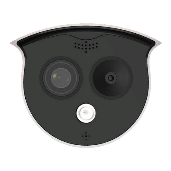
1. Product Introduction 1.1. Product Description Thermal imaging binocular intelligent network camera is a new thermal imaging network camera that integrates network remote monitoring functions, face recognition algorithms, video server functions and high-definition camera functions. It supports visible light and thermal imaging dual video output, human body temperature measurement, face recognition capture and other functions. -
Page 5: Cable Description
1.3. Cable Description ① ② ③ ④ ① Alarm interface: including alarm input and alarm output, a group of inputs, a group of outputs and RS485 (used to connect external devices with RS-485 interface). Alarm Input Alarm Output RS485 485+ 485- ②... -
Page 6: Product Installation
2. Product Installation 2.1. Installation Location Selection (1) The camera is set up right in front of the passage to capture the face. (2) The recommended installation height is about 2 meters, and the recommended viewing angle of the camera is 0~5 degrees. (3) In order to ensure the effect of body temperature detection, the distance between device and personnel collection point should be within 2 meters (range 0.25~3 meters). -
Page 7: Instructions Before Installation
2.3. Instructions Before Installation Before installation, please check whether the equipment in the packing box is intact and all accessories are complete. The wall to be installed should have a certain thickness and can withstand at least 4 times the weight of the camera and mounting accessories. If the device is installed on a concrete wall or ceiling, you need to install expansion screws before installing the bracket. -
Page 8: Wall Mounting
Step 1 There is a TF card slot on the back of the device, then use a phillips screwdriver to unscrew the TF card slot cover. Step 2: Insert the TF card into the card slot slowly, and when you hear a "click"... - Page 9 Step 2 Arrange and connect the power cables, network cables and other cables of the device, and insulate the power cables. Clip the cable into the cable outlet. Align the base hole with the sticker hole, and fix the device to the wall with screws.
-
Page 10: Tripod Mounting
2.5.2. Tripod Mounting Align the screws on the top of the tripod with the mounting holes on the bottom of the camera and lock the screws to fix. Tripod hole 3. Instructions After the IPC is installed, you need to configure functions and set parame- ters for it. - Page 11 The network configuration steps are as follows: Step 1: Open [ Search Tool] (Version 7.2.45.6 and above, please install Search Tool from http://www.herospeed.net). Step 2: Check 192.168.1.168. Step 3: Modify the relevant network parameters such as IP on the right side of...
- Page 12 Step 4: Enter the user name (default is admin) and password (default is admin) of the device. Step 5: Click [Modify] → [Confirm]. Step 6: Click [Refresh] to find the IP address that has been modified, which means that the network configuration is successful. NOTE: When configuring network parameters, ensure that the IPC address and the computer's IPv4 address are on the same network segment.
-
Page 13: Real-Time Preview
3.3. Real-time Preview Enter real-time preview interface after login. Select the play window, click the channel on the left side of the interface, and the play window will play real-time video. 3.4. Parameter Configuration Click [Configuration] to enter the parameter configuration interface of the device, which includes local configuration, system, network, video, image, events, temperature measurement and other functional configurations. - Page 14 3.5. Temperature Measure Configuration Step 1: On the main interface, click [Configuration] → [Temperature measure] → [Temperature measure] to enter the temperature measurement basic setup interface. Step 2: Turn on the temperature measurement function to configure the relevant temperature measurement parameters of Camera 02, and click [Save].
- Page 15 Step 4: Select [Camera 02], draw the bold point (if there is a black body) and reference point, configure related parameters (shutter parameters, temperature compensation, etc.), and click [Save].
- Page 16 Step 7: Click [Save] to complete the configuration. 3.6. iVMS330 Client Access Step 1: Open your browser and visit http://www.herospeed.net/. Step 2: Click [PC Client] → [iVMS330 (Windows)] or [iVMS330 (Mac)] to download the latest version of the video management system [iVMS330].
Need help?
Do you have a question about the OWL256 and is the answer not in the manual?
Questions and answers