Table of Contents
Advertisement
Quick Links
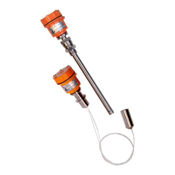
TLC2:
Capacitance Type Level
Transmitter for Liquids
Trumen Technologies Pvt. Ltd.
39 Mangal Nagar, Behind Sai Ram Plaza, Near Rajiv Gandhi
Circle, AB Road, Indore, MP 452 001, India
Phone: +91-731-497 2065
Instruction Manual
sensing matters
Customer Support
Phone: +91-731-656 2425
email: sales@trumen.in
email: support@trumen.in
web:www.trumen.in
®
Advertisement
Table of Contents

Summary of Contents for Trumen TLC2
- Page 1 Capacitance Type Level ® Transmitter for Liquids sensing matters Instruction Manual Customer Support Trumen Technologies Pvt. Ltd. Phone: +91-731-656 2425 39 Mangal Nagar, Behind Sai Ram Plaza, Near Rajiv Gandhi email: sales@trumen.in Circle, AB Road, Indore, MP 452 001, India email: support@trumen.in Phone: +91-731-497 2065 web:www.trumen.in...
-
Page 2: Table Of Contents
Error Indications......................Page5 Electrical Connections - TLC2 (EILV/ERLV)..............Page6 Electrical Connections TLC2 (4-20mA) Loop Output..........Page6 Electrical Connections TLC2 (1 to 5V) Voltage Output..........Page6 Electrical Connections TLC2 (2 to 10V) Voltage Output........... Page6 Annexure-2 Introduction - TLC-SS+ICT 2R/3R (Order code EIR)........... -
Page 3: Operating Principle
Using these values and following equation read C(low) L(high) for 4mA C(high) C(low) L(high) L(low) = L(low) P x {ε(material) ε(air)} mili-Ampere device creates a chart of level to 4-20mA translation. 4 20 CALIB read C(high) for 20mA tlc2-manual-01 www.trumen.in Page 1... -
Page 4: Technical Specification
Process Temp. -20°C ... 100°C (-4°F ... 212°F) Extended Process PTFE Insulation: -30°C ... 250°C (-22°F ... 482°F) Trumen Technologies Pvt.Ltd. Temperature Ceramic Insulation: -30°C ... 600°C (-22°F ... 1,112°F) (extensions & heat sinks required) Process Pressure absolute / max. 15 bar (for ceramic insulation : 1 atm) -
Page 5: Do's And Don'ts
8. Nozzles should never be longer than the inactive / ground length 9. Never climb either by gripping or stepping over either the probe or its aluminium housing 10. Obeserve other safety precautions as required at the place of application tlc2-manual-page03 www.trumen.in... -
Page 6: Troubleshooting
Provide an exclusive earthing to terminal# 3, capacitance enclosure earthing screw and capacitance probe process connection (device mounting screw or flange) Maintenance and Spares Shown on the left are various parts of TLC2 capacitance level switch. Top Cover Separatable parts are Electronic Insert connection terminals 1. - Page 7 Annexure-1 Introduction TLC2 (EILV / ERLV) controls & indicators Process indicating LED status TLC2 Calibration & configuration switches Connecting terminals 1500pF turn-on Range to set External Earthing Terminal 4200pF status increase decrease/damping connection terminals (100%) 20mA/5V/10V 12 to 60 VDC...
-
Page 8: Connection Diagrams Tlc2 ((Eilv/Erlv)
Annexure-1 Connection Diagrams - TLC2 (EILV/ERLV) For current output 4-20mA TLC2 1. Grounded Load 1500pF turn-on Range to set 4200pF status increase decrease/damping (100%) 20mA/5V/10V 12 to 60 VDC (0%) 4mA/1V/2V 4..20mA o/p 1..5V 2..10V* *Min Supply U > 21.5V... -
Page 9: Full Calibration (100% Or 20Ma Calibration)
Annexure-1 Calibration TLC2 (EILV/ERLV) Full calibration (100% or 20mA Calibration) TLC2 TLC2 TLC2 1500pF 1500pF 1500pF turn-on turn-on turn-on to set Range to set Range to set Range 4200pF 4200pF 4200pF status increase status increase status increase decrease/damping decrease/damping decrease/damping... - Page 10 Annexure-1 Operation Matrix TLC2 (EILV / ERLV) This model is best suitable for continuous current level measurement, as well as continuous voltage measurement with option 1 to 5V and 2 to 10 VDC. M aterial & Switching Calibration Current Voltage...
-
Page 11: Status Led Indications
Error Indications 1. Blinking once per two seconds : No Error 2. Blinking rapidly rapidly : Indicating too high capacitance at probe (Error) Cause: Due to probe is too long for TLC2 in conductive liquid or water. TLC2 1500pF turn-on... -
Page 12: Electrical Connections Tlc2 (1 To 5V) Voltage Output
Annexure-1 Electrical Connections - TLC2 (EILV / ERLV) electrical connections TLC2 TLC2 increase DC Supply min. 12V Not used max. 60V electrical connections TLC2-(1-5V) Voltage Output TLC2 increase Not used DC Supply Voltage output on terminals 2,4 min. 12V Voltmeter/Analog input resistance max.
Need help?
Do you have a question about the TLC2 and is the answer not in the manual?
Questions and answers