
Related Manuals for DORSEY BENCHMARK 16H


Summary of Contents for DORSEY BENCHMARK 16H
- Page 1 BENCHMARK 16H OWNERS MANUAL Revised: Nov. 2015 Dorsey Metrology International Optical Metrology Division 53 Oakley Street Poughkeepsie, New York 12601 Telephone: (845) 454-3111 Fax: (845) 454-3140...
-
Page 2: Table Of Contents
CONTENTS Manual valid from S/N 0205/845 forward CONTENTS PAGE 1 Section No.. Introduction 1 . 0 Location 1 . 1 Operating Conditions 1 . 2 Electrical supply Information 1 . 3 Un-Packing Instructions 1 . 4 Machine Installation and Setup 2 . -
Page 3: Contents
CONTENTS Manual valid from S/N 0205/845 forward CONTENTS PAGE 2 Maintenance 6 . 0 Cleaning the lenses, screen and mirrors 6 . 1 Lamps replacement and adjustment 6 . 2 Fuse replacement 6 . 3 6 . 4 Magnification and Measuring Accuracy check Readout Accuracy 6 . -
Page 4: Introduction
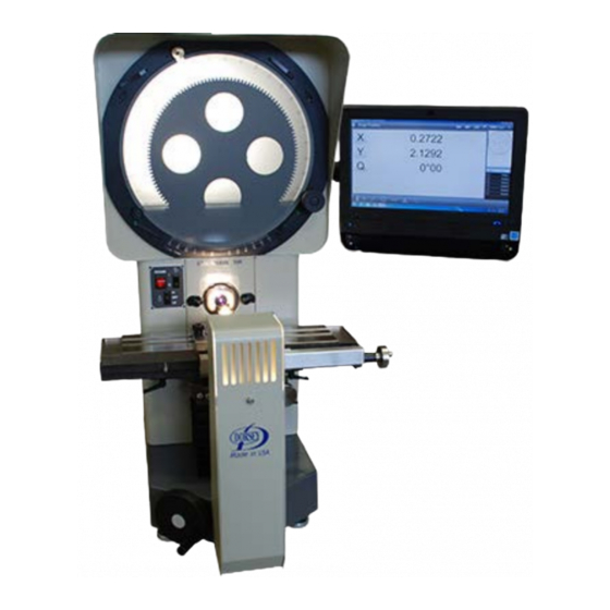
1.0 INTRODUCTION The Benchmark 16H Optical Comparator is a compact bench mounted unit with a horizontal lens axis and a two mirror optical system, projecting the “industry standard” erect and reversed image on the screen. The unit is designed to give the maximum possible screen size and work stage capacity while retaining good operator access to the controls and screen viewing area. -
Page 5: Location
1 . 3 Electrical Supply Information The standard Benchmark 16H is supplied to accept 110-120VAC, 50-60 Hz main power. It may also be configured to accept either 220-240VAC, 50- 60HZ. Unless clearly labeled (next to the power input plug) this unit is configured for 110-120VAC,50-60Hz. -
Page 6: Unpacking Instructions
Inspect for shipping damage Please follow the instructions listed below to properly unpack your optical comparator. If shipping damage becomes evident or questions arise during installation please call Dorsey Metrology International at 1-800-549-4243 for immediate assistance. 1) Inspect the cardboard outer box and pallet for evidence of shipping damage. If evidence is apparent immediately annotate damage on the receiving documentation and notify Dorsey Metrology International at the number listed above. - Page 7 2.0 Machine Installation and Setup Section One 1) Once the machine is in place on the workbench (See “Unpacking Instructions”) cut and remove the Y-Axis shipping lock. It is a strap wrapped around the machine preventing the Y-Axis from moving. 1a) Level the machine front to back and side to side, using a standard quality level placed on the stage.
-
Page 8: Machine Installation And Setup
Machine Installation and Setup Section Two 2 .1 “Heidenhain Setup Instructions” 7) Attach the Digital Readout mounting arm to the right side of the comparator using four M4 socket head cap screws provided. 3MM hex wrench needed. 8) Mount the Digital Readout onto the DRO base using the four 10-32 X 3/8” socket head cap screws provided. -
Page 9: Installation And Setup Continued
2. Machine Installation and Setup Section Three 2 . 3 Installation and Setup Continued 15) With the main (Red) power switch on and the cardboard cover removed from the lens opening, test the profile light switch by briefly switching to high and low. Center position is off. CAUTION: without a lens in the machine the screen will be very bright. - Page 10 2. Machine Installation and Setup Section Four Squaring the focus axis example one Squaring the focus axis example two 19) Verify screen magnification, adjust as required. Qualified personnel only 20) Verify DRO error compensation, adjust as required. Qualified personnel only 21) Your comparator was fully inspected and calibrated to a high degree of accuracy before it left the factory.
-
Page 11: Fitting Projection Lenses
Dorsey Metrology International is also able to offer advice and manufacturing facilities for special custom work-holding fixtures and or custom options. -
Page 12: Safety
3.0 SAFETY This equipment has been designed and manufactured so far as is reasonably practical to allow its safe operation when used in accordance with the following instructions. The equipment must be used in a location that does not constitute a hazard, where the operator and maintenance staff have free access to the control and maintenance of the equipment, and are not subject to any external hazards. -
Page 13: Operating
4.0 OPERATING Section one 4 . 1 Switching On Ensure that the projector is connected to the proper power supply. (Refer to the “Additional Electrical Information” page for help). The lamps are controlled by rocker switches located on the front panel of ... -
Page 14: Surface Illumination
4. OPERATING Section two 4 . 5 Surface Illumination Illumination of surface features on solid objects is achieved through the use of high intensity fiber optic light guides. These guides are adjustable and can be extended by pulling on the cable ends protruding from either side of the lens mount. -
Page 15: Helix Adjustment
4. OPERATING Section three 4 . 7 Stage Helix Adjustment The top of the focus slide has a stage helix adjustment, which allows the stage to be rotated horizontally. To do this the 2 locking clamps located beneath the stage must first be loosened. The stage can now be rotated +/- 15 degrees. -
Page 16: Additional Electrical Information
ELECTRICAL INFORMATION 5 . 1 Connecting Electrical Supply The standard Benchmark 16H is supplied to accept 110-120VAC, 50-60 Hz main power. (NOTE: See section 1.4 for power requirements). It may also be configured to accept 220-240VAC main power. Use the following procedure to convert the machine power module for alternative power input. - Page 17 5 . ADDITIONAL ELECTRICAL INFORMATION CONTINUED “120” 7. Insert the card back in so when the lever is in the down position either “240” is showing if your power supply is 110-120 VAC or is showing if your power supply is 220-240 VAC. 8.
- Page 18 6.0 MAINTENANCE SECTION ONE 6 . 1 Cleaning the lenses, screen and mirrors Lenses: Any accumulated dust must be removed from the surface of the lenses with a photographic lens brush. The surface of the inner lens (projection or condenser) must not be touched.
- Page 19 6. MAINTENANCE SECTION TWO DANGER! - When using methanol or alcohol for cleaning disconnect the comparator from the power source and remove all sources of ignition from the area. Wait for all vapors to thoroughly evaporate before re- connecting the power. WARNING! –...
-
Page 20: Maintenance
6. MAINTENANCE SECTION THREE 6 . 2 Lamp Replacement and Adjustment WARNING! This must be done with the power switched off and the lamp cold. PROFILE LAMP To change the lamp first remove the lamp house cover. Remove the old bulb by grasping and pulling the bulb directly up. - Page 21 6. MAINTENANCE SECTION FOUR SURFACE LAMP To change the surface lamp, first remove the lamp house cover. The bulb is located at the bottom of the lamp house. To remove the bulb, grasp and lift the bulb ejection wire lever to eject bulb. Remove the new replacement bulb from its box, Do not touch the small bulb inside the reflector housing.
-
Page 22: Fuse Replacement
6. MAINTENANCE SECTION FIVE 6 . 3 Fuse Replacement The main fuse on the 16H is located inside the power input module on the back of the machine. It is a 10A 250V “Slo-Blo” ceramic fuse. Remove the power cord and slide the clear plastic cover up to access the fuse. - Page 23 It is considered to be out of the scope of the average user to maintain the proper calibration equipment and training required to accurately calibrate an optical instrument. Dorsey Metrology International Optical Metrology Division (OMD) provides this service and training classes on calibration.
-
Page 24: Readout Accuracy
6. MAINTENANCE SECTION SEVEN 6 . 5 Readout Accuracy The accuracy of your digital readout system is dependent on many items. Factors such as stage accuracy and condition, scale accuracy and condition, method of inspection and operator interpretation. All will determine the outcome of any accuracy test. - Page 25 6. MAINTENANCE SECTION EIGHT The points of lubrication on the 16H comparator are as follows. X Axis stage bearing rollers and ways. Clean bearing ways with a lint free cloth dampened with WD40. Wipe dry with a clean lint free cloth. Leaving just a small amount of residual lubrication.
- Page 26 6. MAINTENANCE SECTION NINE X Axis leadscrew and leadscrew bearing blocks. Isolate the X axis leadscrew with rags and spray the leadscrew with WD-40 to remove built up dirt. Wipe to clean with a clean lint free cloth or soft brush (like a tooth brush).
- Page 27 6. MAINTENANCE SECTION TEN Focus axis Lubricate the focus bearing rollers and ways the same as the above X Axis bearings. Lubricate the focus leadscrew, and lead nut with “high pressure Acme screw grease” or white lithium grease. The focus bushing is a permanently lubricated bronze type.
- Page 28 6. MAINTENANCE SECTION ELEVEN Y Axis leadscrew Y Axis nut Y Axis Gears Y axis bearing rollers and ways are located under two bellows protectors and under normal conditions do not need any lubrication. Lubricate the Y axis leadscrew and nut with high pressure acme ...
-
Page 29: Technical Specifications
375 Lbs. Standard model. 445 Lbs. Extended Stage model. Power Supply (required input): AC 110 volt 50/60 Hz (Can convert to 220V 50/60Hz) Accessories included with Benchmark 16H: Line Power Cord, Readout Power Cord, Condenser Lens, Lifting handles. Lens system : 1/8 turn “Quick Change” type... -
Page 30: Lens Specifications For 16" Machines
7. TECHNICAL SPECIFICATIONS SECTION TWO 7 . 1 Lens Specifications for 16” Machines Projection Working Workpiece Focal Plane Lens Distance Diameter 5.43” 10” Lens Condenser 3.25 3.22 2.75 13” 31.25x 2.20 4.35 2.00 100x 1.69 3.25 7 . 2 FOOT PRINT 16H Manual Page 30 Revised: 11/2015... -
Page 31: Wiring Diagram
7. TECHNICAL SPECIFICATIONS 7.3 16H WIRING DIAGRAM 16H Manual Page 31 Revised: 11/2015... -
Page 32: System Configuration Checklist
When unpacking your instrument, insure all items have been included in this shipment BEFORE DISCARDING ANY PACKING MATERIAL. Back ordered items will be noted on the packing slip attached to the shipping container. MODEL:____________Serial No. __________________ Dorsey Work Order Number:______________ STANDARD ACCESSORIES Screen... - Page 33 Optical Metrology Division TEL: 845-454-3111 FAX: 845-454-3888 Thank you for the purchase of a Dorsey Metrology International, OMD product. So that you receive a full 2 year limited warranty on your system, please read and return the Registration/RMA form immediately upon receipt. You are entitled to a full 2 year limited warranty beginning from the date of receipt of your system.
-
Page 34: Limited Warranty Policy Registration / Rma Form
53 Oakley Street, Poughkeepsie, New York 12601 Optical Metrology Division TEL: 845-454-3111 FAX: 845-454-3888 To obtain service, the purchaser must first contact Dorsey Metrology International via phone or fax who will at their discretion determine which of two procedures must be followed. RMA Procedure...
Need help?
Do you have a question about the BENCHMARK 16H and is the answer not in the manual?
Questions and answers