Table of Contents
Advertisement
Quick Links
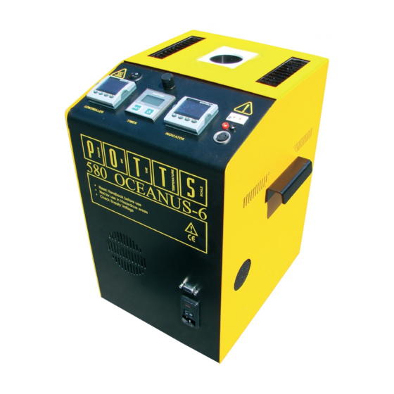
OCEANUS-6 SERIES
MODEL 580
User Maintenance Manual/Handbook
Isothermal Technology Limited, Pine Grove, Southport, PR9 9AG, England
Tel: +44 (0)1704 543830 Fax: +44 (0)1704 544799 Internet: www.isotech.co.uk E-mail: info@isotech.co.uk
The company is always willing to give technical advice and assistance where appropriate. Equally, because of the programme of continual
development and improvement we reserve the right to amend or alter characteristics and design without prior notice. This publication is for
information only.
Page 1 of 39
Oceanus-6 Series Model 580 Iss.08 – 04/15
Advertisement
Table of Contents

Subscribe to Our Youtube Channel
Related Manuals for Isotech OCEANUS-6 Series

Summary of Contents for Isotech OCEANUS-6 Series
- Page 1 Isothermal Technology Limited, Pine Grove, Southport, PR9 9AG, England Tel: +44 (0)1704 543830 Fax: +44 (0)1704 544799 Internet: www.isotech.co.uk E-mail: info@isotech.co.uk The company is always willing to give technical advice and assistance where appropriate. Equally, because of the programme of continual development and improvement we reserve the right to amend or alter characteristics and design without prior notice.
-
Page 2: Table Of Contents
CALIBRATION DATA EXAMPLE ..............................25 CONNECTING A CURRENT TRANSMITTER (UP TO 20MA) ....................25 SELECTING CONFIGURATION LEVEL ........................... 26 TESTING THERMOSTATS ................................ 27 USING THE PC INTERFACE ................................. 28 Page 2 of 39 Oceanus-6 Series Model 580 Iss.08 – 04/15... - Page 3 INITIAL TESTING................................... 32 IMPORTANT NOTICE ................................32 MAINTENANCE .................................... 33 FIGURE 1 ......................................34 APPENDIX 1: OCEANUS-6 SERIES TROUBLE SHOOTING ....................... 35 Unit fails to operate............................... 35 Will not cool properly ............................35 Indicator reads incorrectly ............................ 35 Unit unstable ................................. 35 Cannot establish PC Communications ........................
-
Page 4: Guarantee
INTERFERENCE WITH OR FAILURE TO PROPERLY MAINTAIN THIS INSTRUMENT MAY INVALIDATE THIS GUARANTEE RECOMMENDATION The life of your ISOTECH Instrument will be prolonged if regular maintenance and cleaning to remove general dust and debris is carried out. We recommend that this instrument to be re-calibrated annually. -
Page 5: Emc Information
The Blue conductor should be connected to Neutral and the Brown conductor to Live (Line). Warning: Internal mains voltage hazard. Do not remove the panels. There are no user serviceable parts inside. Contact your nearest Isotech agent for repair. Voltage transients on the supply must not exceed 2.5kV. -
Page 6: Health And Safety Instructions
If cased, do not return the apparatus to its carrying case until the unit has cooled. There are no user serviceable parts inside. Contact your nearest Isotech agent for repair. Ensure materials, especially flammable materials are kept away from hot parts of the apparatus, to prevent fire risk. -
Page 7: Cautionary Note
CAUTIONARY NOTE ISOTECH PRODUCTS ARE INTENDED FOR USE BY TECHNICALLY TRAINED AND COMPETENT PERSONNEL FAMILIAR WITH GOOD MEASUREMENT PRACTICES. IT IS EXPECTED THAT PERSONNEL USING THIS EQUIPMENT WILL BE COMPETENT WITH THE MANAGEMENT OF APPARATUS WHICH MAY BE POWERED OR UNDER EXTREMES OF TEMPERATURE, AND ARE ABLE TO APPRECIATE THE HAZARDS WHICH MAY BE ASSOCIATED WITH, AND THE PRECAUTIONS TO BE TAKEN WITH, SUCH EQUIPMENT. -
Page 8: Unpacking And Initial Inspection
THE APPARATUS MUST BE CORRECTLY EARTHED (GROUNDED) The units on/off switch is located on the power inlet. Take care NOT to switch the unit off when it is hot - allow to cool first. Page 8 of 39 Oceanus-6 Series Model 580 Iss.08 – 04/15... -
Page 9: Oceanus-6 Model 580 'Do's And Don'ts
DO NOT try to straighten the working standard, it is deliberately bent so that it does not interfere with the sensors you are calibrating. Page 9 of 39 Oceanus-6 Series Model 580 Iss.08 – 04/15... -
Page 10: Introduction
This is a common method but is unsafe since the control sensor is inaccessible in the wrong place to give correct temperature of the insert For these reasons it fails to satisfy ISO9000 and gives large uncertainties. Page 10 of 39 Oceanus-6 Series Model 580 Iss.08 – 04/15... -
Page 11: Using The Indicator (Not Basic (B) Model)
It means that the calibrator does not need calibrating only the indicator and its calibrated sensor need re-calibration, but this option is more bulky, expensive and less portable than above. It also meets ISO9000 requirements. Page 11 of 39 Oceanus-6 Series Model 580 Iss.08 – 04/15... -
Page 12: Mode Of Operation
The stirrer speed control is set ON and to the mid position. If necessary the speed to can be adjusted to give the optimum value for a particular application, this position should be found experimentally and then noted for future use. Page 12 of 39 Oceanus-6 Series Model 580 Iss.08 – 04/15... -
Page 13: Stirred Ice Bath
A calibrated probe (part number 935-14-84) is placed in the pocket of the surface sensor insert and connected to the temperature indicator. Surface sensors are placed on top of the insert and when stable compared to the calibrated probe. Page 13 of 39 Oceanus-6 Series Model 580 Iss.08 – 04/15... -
Page 14: Adjusting The Timer
ADJUSTING THE TIMER Page 14 of 39 Oceanus-6 Series Model 580 Iss.08 – 04/15... -
Page 15: Using Water & Gallium Fixed Point Cells
Set the Oceanus-6 to give a well temperature of approximately 32°C. Monitor the Cell until the Gallium starts to melt, at this stage the well temperature can be lowered to 30.5°C which will give a long melt plateau. Page 15 of 39 Oceanus-6 Series Model 580 Iss.08 – 04/15... -
Page 16: Slim Gallium Cell
The magnitude of these effects may be checked (i) by reducing the immersion depth and (ii) by making measurements at two currents through the thermometer. SLIM GALLIUM CELL Please see separate handbook for this cell. Page 16 of 39 Oceanus-6 Series Model 580 Iss.08 – 04/15... -
Page 17: Thermometric Fixed Points (A Tutorial Note)
Alternatively, once the melt has begun the water in the well can be replaced by warm water at say 40°C to initiate a melt round the re-entrant tube. See CCT96/8 for additional guidance. Page 17 of 39 Oceanus-6 Series Model 580 Iss.08 – 04/15... -
Page 18: Hint On How To Measure The True Temperature Inside The Accessories Supplied With The Oceanus-6 Series
The Industrial thermometer is placed in the accessory or insert and is compared to the True Temperature as indicated by the reference thermometer. An insert will typically have a 1% immersion error. For more details see - Depths of Immersion. Tavener J. P. Volume 9.2. Isotech Journal of Thermometry pages 79-87. Page 18 of 39... -
Page 19: Specification
Standard Insert Hole Dimensions 6 x 8mm Insert Options Adjustable Height Equalising Block Special drilling available to customer requirements. Blank Dimensions (not including handle) Height 430mm Width 310mm Depth 300mm Weight 17Kg Page 19 of 39 Oceanus-6 Series Model 580 Iss.08 – 04/15... -
Page 20: Oceanus-6 Performance Graph
OCEANUS-6 PERFORMANCE GRAPH Page 20 of 39 Oceanus-6 Series Model 580 Iss.08 – 04/15... -
Page 21: Operating The Oceanus-6
The setpoint can be seen by pressing either the UP and DOWN key. The Setpoint ramp rate operates when the bath is heating and cooling. Page 21 of 39 Oceanus-6 Series Model 580 Iss.08 – 04/15... -
Page 22: Instrument Address
Check that any sensor placed into the Oceanus-6 is suitable for the temperature range. Sensors can be damaged if taken outside their normal operating limits. The desired sensor type is easily set, press the Scroll key until the upper display indicates, inPt Page 22 of 39 Oceanus-6 Series Model 580 Iss.08 – 04/15... -
Page 23: Enabling / Disabling Custom Calibration
User calibration can make a significant difference to the accuracy of the instrument, and this REM beacon provides a clear and continuous indication of the calibration status. Isotech will configure and set user calibration when the Dry Block is ordered with a temperature sensor. -
Page 24: Monitoring The Indicator Status
The indicator can be configured with up to five custom calibration points; the points contain "data pairs". First the temperature (point) and secondly the Error (offset) at this temperature point. Isotech Dry Block calibration certificates will show the values to suit a particular sensor. -
Page 25: Calibration Data Example
Pnt 1 100 Ofs 1 0.8 Pnt 2 300 Ofs 2 1.1 Pnt 3 500 Ofs 3 2.1 Pnt 4 -999 Ofs 4 0 Pnt 5 -999 Ofs 5 0 Page 25 of 39 Oceanus-6 Series Model 580 Iss.08 – 04/15... -
Page 26: Connecting A Current Transmitter (Up To 20Ma)
The transmitter should be powered externally, a 2.49Ω current sense resistor is fitted internally and this allows the indicator to read mA. From the input type menu select “mV”. Access configuration level. SELECTING CONFIGURATION LEVEL Page 26 of 39 Oceanus-6 Series Model 580 Iss.08 – 04/15... -
Page 27: Testing Thermostats
TESTING THERMOSTATS The Site model can be used the Isotech Cal Notepad software for the testing of thermostats and other thermal switches with volt free contacts. Cal Notepad can capture the temperature at which a switch opens or closes. It can also perform a hysteresis test. -
Page 28: Using The Pc Interface
The Isotech conversion leads are suitable for maximum combined lead lengths of 10M that is adequate for most applications. CONNECTIONS For RS232 use simply connect the Isotech cable, a 9 to 25 pin converter is included to suit PCs with a 25 pin serial converter. RS422 Connections... -
Page 29: Cal Notepad
DEVELOPMENT Cal NotePad was developed by Isothermal Technology using LabVIEW from National Instruments. The license details are shown on the download page and in the Cal Notepad manual. Page 29 of 39 Oceanus-6 Series Model 580 Iss.08 – 04/15... -
Page 30: How To Install Cal Notepad
Should you ever need to uninstall the software then use the Add/Remove Programs option from the Control Panel. PROTOCOL The instruments use the "Modbus Protocol" If required, e.g. for writing custom software the technical details are available from our Document Library at http://www.isotech.co.uk Page 30 of 39 Oceanus-6 Series Model 580 Iss.08 – 04/15... -
Page 31: Diagnostic Alarms
Error 5: Input circuit failure Err5 Consult Isotech Power failure Pwr.F . The line voltage is too low Check that the supply to the controller is within the rated limits Page 31 of 39 Oceanus-6 Series Model 580 Iss.08 – 04/15... -
Page 32: Initial Testing
The Oceanus-6 uses Solid State Heat Pumps to drive the temperature range. These pumps to drive the temperature range. These pumps are very fragile and should be considered when lowering heavy objects into the well. Page 32 of 39 Oceanus-6 Series Model 580 Iss.08 – 04/15... -
Page 33: Maintenance
Maintenance is limit to keeping the apparatus and the calibration volume clean and free from debris. There are no internal user serviceable parts. Repair and maintenance must be carried out by Isothermal Technology Limited or an approved agent. Page 33 of 39 Oceanus-6 Series Model 580 Iss.08 – 04/15... - Page 34 Power Entry and Fuse On/Off Switch Note: Only connect a thermocouple or platinum resistance thermometer to the input connectors. Ensure that only one sensor is connected at any time. Page 34 of 39 Oceanus-6 Series Model 580 Iss.08 – 04/15...
-
Page 35: Appendix 1: Oceanus-6 Series Trouble Shooting
APPENDIX 1: OCEANUS-6 SERIES TROUBLE SHOOTING Unit fails to operate Check fuse, Figure 1. If fuse blows repeatedly consult Isotech or local agent. Will not cool properly Check room temperature. Minimum operating temperature of 45°C below ambient, e.g. -25°C at room temperature of 20°C. -
Page 36: Appendix 2: Indicator Configuration (Reference Only)
User Cal Offset 4 0.00 OFS5 User Cal Offset 5 -99.00 Note: User Cal values are unique to each instrument. If available set values to those from calibration certificate Page 36 of 39 Oceanus-6 Series Model 580 Iss.08 – 04/15... -
Page 37: Config.al
Module function NONE (0) SEnS Sense of Output NOR (0) Config.2A Name Description Value Module Identity LOG (3) Func Module function NONE (0) SEnS Sense of Output NOR (0) Page 37 of 39 Oceanus-6 Series Model 580 Iss.08 – 04/15... -
Page 38: Appendix 3: Accessories Parts List
Surface Sensor Insert 580-02-11 Surface Sensor Probe 935-14-84 OPTION 6 Slim Gallium Cell 17401M Slim Water Triple Point Cell C20 Oil 580-06-09 Standard Probe for On-site Model 935-14-85 Carrying Case 931-22-58 Page 38 of 39 Oceanus-6 Series Model 580 Iss.08 – 04/15... -
Page 39: Liquid In Glass Thermometer Support Kit - 580-06-00
LIQUID IN GLASS THERMOMETER SUPPORT KIT - 580-06-00 'O' RING GANTRY DISC SUPPORT COLLAR THERMOMETER GANTRY LIQUID CONTAINER LIQUID VOLUME LIQUID CONTAINER KIT - 580-06-07 THERMOMETER SENSOR GUIDE LIQUID CONTAINER MAGNETIC STIRRER Page 39 of 39 Oceanus-6 Series Model 580 Iss.08 – 04/15...
Need help?
Do you have a question about the OCEANUS-6 Series and is the answer not in the manual?
Questions and answers