
Summary of Contents for Massoth DiMAX 1203B
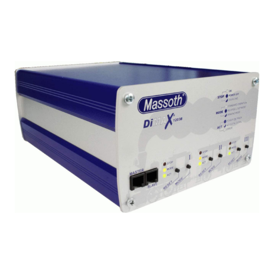
- Page 1 MASSOTH DiMAX 1203B Digital Booster ® Digital Booster 3 x 4 Amps for NMRA compatible model railroads Item No.: 8141001 Version 1.00 – 12/07 DiMAX 1203B Digital Booster ®...
-
Page 2: Table Of Contents
MASSOTH Index Page General Description Summary of Functions III. Layout of Terminals Please read this first! Safety Details and Warnings Warranties and Guaranties Warranty Claims Service and Customer Support Scope of Supply Getting started Hook Up Power Supply Fuse Track Hook Up Hook Up of Control Components ®... -
Page 3: General Description
An overload protection and a temperature controlled fan are integrated. The DiMAX 1203B Digital Booster provides 3 operational modes: booster, booster with a re- verse loop function, and booster with a braking function. In addition the DiMAX 1203 is inde- pendant of any digital protocol which makes it usable with NMRA compatible systems or any other digital system. -
Page 4: Please Read This First
1.1.11 Visually inspect your digital components regularly, remove damaged items immediately. 1.1.12 The right to change this product in accordance with technical progress is reserved by MASSOTH ELEKTRONIK, Seeheim, Germany. We can not compensate for damages resulting from inappropriate handling, non-observance of this manual, operation with altered or damaged items or items not suitable for the DiMAX®... -
Page 5: Warranty Claims
1.3 Warranty Claims Valid warranty claims will be serviced without charge within the warranty period. To initiate a warranty claim, please contact your dealer or MASSOTH ELECTRONICS USA for an RMA (Return Merchandise Authorization). MASSOTH ELECTRONICS USA cannot be responsible for return shipping charges to our repair facility. -
Page 6: Getting Started
MASSOTH Getting started The following chapter describes the hook-up and the first operation of the DiMAX ® 1203B Di- gital Booster. Hook Up Place the DiMAX® 1203B Digital Booster in an appropriate place. The DiMAX® 1203B Digital Booster should not be placed close to a radiator, any heating device or in direct sunlight. At all times ensure sufficient ventilation and a proper temperature range for the DiMAX®... -
Page 7: Power Supply
MASSOTH Illustration 2: The rear panel of the DiMAX® 1203B Digital Booster Power Supply Illustration 3: Power Terminal DiMAX 1203B Digital Booster ®... -
Page 8: Fuse
Connect the power supply cables to the green 2-pole connector with a regular screw driver and insert the connector into the main power socket on the rear panel of the DiMAX 1203B Digital Booster (as shown in illustration 3). Do not tin the cables! Utilize core cable ends or twist the cables well before tightening the mounting screws. -
Page 9: Hook Up Of Control Components
MASSOTH Hook up of Control Components The DiMAX ® 1203B Digital Booster features two terminals on the front panel. These terminals may be utilized to connect a Central Navigator (see note page 2), DiMAX bus components as e.g. feedback module, train detector, or the DiMAX transducer to the DiMAX ®... - Page 10 MASSOTH See the manual of your central station for the correct wiring! The DiMAX ® 1203 Booster connects to a DiMAX ® or LGB ® central station (MTS II or III) via the 4-pole booster bus terminal. Utilize the booster interface cable to hook up the booster to the central station.
-
Page 11: Led Status Indications And Control Panel
MASSOTH LED Status Indications and Control Panel The LED indicators show the status of the operation and the actual status of the layout. There are three LED indicators provided per channel. Illustration 6 shows all the variations of indica- tions possible: Illustration 6: LED Status Indications The respective modes are explained in chapter 5. -
Page 12: The First Switch-On
MASSOTH The First Switch-On 1203 Booster with a central station, the central station must be In case you use the DiMAX ® switched on first. Switch on the power supply for the DiMAX ® 1203 Booster. After the power up the LED indicators switch from red to green. The lower green LEDs will be illuminated provided the central station is not in the emergency stop mode and the booster is connected correctly to the central station. -
Page 13: Operational Mode 1 (Booster)
MASSOTH Operation Mode 1 (Booster) In this mode the DiMAX ® 1203 Booster works as a regular booster (Illustr. 7). In lieu of the 800Z you may use a DiMAX ® 1210Z, a DiMAX ® 1200Z, LGB ® MTS II or III. The hook-up of a Lenz ®... -
Page 14: Connecting The Outputs In Parallel
7 Amps continuously, three outputs deliver approx. 10 Amps conti- nuously. Important: The channels need to be connected in the same polarity! Otherwise com- ponents connected to the DiMAX 1203B might be damaged or destroyed as well as the booster itself. The wiring diagram is shown in illustration 9. -
Page 15: Operational Mode 2 (Booster With Reverse Loop Function)
MASSOTH Operation Mode 2 (Booster reversing loop automation) In mode 2 the DiMAX ® 1203B Booster is operating as a reversing loop module. Illustration 10 shows a typical wiring diagram. In this setup channel 1 is working in mode 2 (reversing loop) and channel 2 is working in mode 1 (booster). -
Page 16: Operational Mode 3 (Booster With Braking Function)
MASSOTH Operation Mode 3 (Booster with braking function) Illustration 11: Wiring diagram with mode 3 (braking function) Mode 3 features a brake and stop function. Illustration 12 shows the typical setup. A patented controlling process facilitates the use of all loco functions while the train is in the braking sec- tion. - Page 17 MASSOTH Special Function “Slow Speed“ in Mode 3 You may also set up a slow speed section with the DiMAX ® 1203 Booster. See the wiring diagram and setup in illustration 13. Illustration 12: Wiring Diagram in Mode 3 with slow speed section and stop function Channel 3 operates in mode 1 (booster), channel 2 works in mode 3 (braking function “slow...
-
Page 18: Operation With Central-Navigator
MASSOTH the warning signal and trigger the first track contact. This contact operates the first relay which changes the power supply of block 2 to channel 2 and the train changes subsequently to slow speed accordingly. After passing the second track contact the second relay is swit- ched and block 2 is powered by channel 1 which will stop the train as channel 1 is working in the stop function. -
Page 19: Operation With Lenz ® Central Stations
MASSOTH Operation with Lenz Central Stations ® Illustration 14 shows how to hook-up the DiMAX ® 1203 Booster to a Lenz ® Central Station. Please note that the CDE cable is connected correctly! Illustration 13: Wiring Diagram in mode 1 with a Lenz® Central Station This wiring diagram is also valid for all other central stations featuring a CDE-Interface. -
Page 20: Operation With Other Central Stations
MASSOTH Operation with other Central Stations Illustration 15 shows how to hook-up the DiMAX ® 1203 Booster to central stations of other manufacturers. Please note that the track power connector of the central station must never be connected to one of the outputs of the DiMAX ®... -
Page 21: Glossar
DCC system. The various bus systems being currently utilized by different manufacturers are typically not compatible. For example, the bus system for Massoth components is called the DiMAX bus. The bus system for Lenz is XpressNet. The bus system for Digitrax is LocoNet. - Page 22 Basic systems, like LGB’s MTS are limited to 22 locomotive addresses and 128 switch decoder addresses. More sophisticated systems, like the Massoth DiMAX, are capable of operating up to 10,239 locomotive addresses and 2,048 switch decoder addresses.
- Page 23 DCC allows the central station to send 14, 28 and 128 speed step commands to mobile (locomotive) decoders. Basic decoders (e.g., LGB 55020) and central stations (e.g., LGB 55000, 55005) only support 14 speeds steps. Massoth central stations and decoders support 14, 28 and 128 speed steps.
-
Page 24: Technical Specifications
All other trademarks printed are registered trademarks as well. No parts of this work may be reproduced or transmitted in any form or by any means, electronic or mechanical, including photocopying and recording, or by any information storage or retrieval system without the prior written permission by Massoth Elektronik GmbH unless such copying is expressly permitted by federal copyright law.
Need help?
Do you have a question about the DiMAX 1203B and is the answer not in the manual?
Questions and answers