Advertisement
Quick Links
DIVISION OF TINKER & RASOR
2828 FM 758, NEW BRAUNFELS, TX 78130 TEL: (830) 253-5621
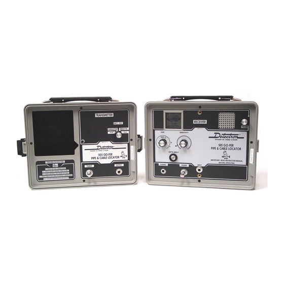
CONTROLS AND FUNCTIONS
RECEIVER
A.
Headphone Receptacle
Allows for use of headphones. Inserting headphone plug turns receiver "On".
B.
Power "On-Off" Switch
"Pull" to turn receiver "On" when loudspeaker operation is desired.
C.
45° Depth Level Indicator
Provides a fast and accurate means of positioning the receiver at 45° for determining depth of buried pipes or cables.
D.
Gain Switch
Battery test position gives an indication of battery condition on signal intensity meter. "L', "M", and "H" positions program the
receiver for low, medium or high gain.
E.
Sensitivity Control
Controls the amount of sensitivity during operation.
F.
Visual Indicator — Battery Test Meter
Gives direct visual indication of signal intensity. Also used for visual indication of receiver battery condition.
G.
Handle Mounting Receptacle
Threaded receptacle for mounting Receiver on carrying handle.
H.
Audio Loudspeaker
Given audio indication of signal intensity.
I.
NEW! Volume Control
Regulates volume without affecting sensitivity.
J.
Handle Mounting Receptacle
Threaded receptacle for mounting receiver on carrying handle
K.
Input Terminal
For use with accessories such as the TS/8 and the 501 Induction Clamp.
TRANSMITTER
L.
Handle Mounting Receptacle
Threaded receptacle for mounting transmitter on carrying handle.
M
Battery Test Lamp
Gives lighted indication of Transmitter battery condition.
N.
Conductive-Inductive Switch and Signal Identifier.
Function switch for desired method of operation. "Conductive" position for direct coupling to pipe and "Inductive" position for
"On-handle" operation and inductive coupling to pipe. Center position provides for testing battery. Note: This switch also activates
the signal interrupter, allowing easier identification of transmitted signals under conditions of foreign noise and high interference.
O.
Power "On-Off" Switch
"Pull" to turn Transmitter "On"..
P.
Output Jack
Jack for attaching the ground plate cable, providing a transmitter ground for direct connection (conductive) operations and for
attaching ground plate and other accessories.
Q.
Carrying Case
ACCESSORIES
R.
Headphones
For optional use. Built-in loudspeaker in Receiver is automatically disconnected when headphones are used.
S.
Ground Plate and Conductive Clamp
Provides transmitter ground for direct connection (conductive) operations and means of direct coupling the transmitter to the
pipe.
T.
Carrying Strap
Used to operate instrument "on-handle" at ground level for greater depth penetration and sensitivity.
U.
Carrying Handle (Transmitter End)
V.
Carrying Handle (Center Section)
W.
Carrying Handle (Receiver End)
Web: www.tinker-rasor.com
P
I
RODUCT
NSTRUCTIONS
M
505 "G
ODEL
O
E-mail: Info@tinker-rasor.com
– 1 –
-F
"
ER
www.detectron.com
Advertisement

Summary of Contents for Tinker & Rasor 505 GO-FER
- Page 1 DIVISION OF TINKER & RASOR www.detectron.com 2828 FM 758, NEW BRAUNFELS, TX 78130 TEL: (830) 253-5621 RODUCT NSTRUCTIONS 505 “G ” ODEL CONTROLS AND FUNCTIONS RECEIVER Headphone Receptacle Allows for use of headphones. Inserting headphone plug turns receiver “On”. Power “On-Off” Switch “Pull”...
-
Page 2: General Information
DIVISION OF TINKER & RASOR www.detectron.com 2828 FM 758, NEW BRAUNFELS, TX 78130 TEL: (830) 253-5621 RODUCT NSTRUCTIONS ASSEMBLY INSTRUCTIONS (ON HANDLE) OPERATION STEP ONE: Assemble instrument as illustrated. STEP TWO: Read condensed instructions on RECEIVER panel and page 3 of operating instructions. Make adjustments accordingly. - Page 3 DIVISION OF TINKER & RASOR www.detectron.com 2828 FM 758, NEW BRAUNFELS, TX 78130 TEL: (830) 253-5621 RODUCT NSTRUCTIONS Attach handle to RECEIVER and TRANSMITTER as shown on page 2. Pull RECEIVER power switch to “ON” for loudspeaker operation. If headphones are desired, simply plug in headphones and RECEIVER will be turned on automatically.
- Page 4 DIVISION OF TINKER & RASOR www.detectron.com 2828 FM 758, NEW BRAUNFELS, TX 78130 TEL: (830) 253-5621 RODUCT NSTRUCTIONS Pull RECEIVER power switch to “ON” for loudspeaker operation. If headphones are desired, simply plug in headphones and RECEIVER will be turned on automatically. Set RECEIVER “GAIN”...
- Page 5 DIVISION OF TINKER & RASOR www.detectron.com 2828 FM 758, NEW BRAUNFELS, TX 78130 TEL: (830) 253-5621 RODUCT NSTRUCTIONS TYPICAL PIPE DETECTION PROBLEMS AND THEIR SOLUTIONS Locating unknown pipe using the locator inductively with handle (PAGE 6). Locating unknown pipes and determining their general direction inductively without handle (PAGE 7).
- Page 6 DIVISION OF TINKER & RASOR www.detectron.com 2828 FM 758, NEW BRAUNFELS, TX 78130 TEL: (830) 253-5621 RODUCT NSTRUCTIONS largely dependent on proper usage of the SENSITIVITY control. If SENSITIVITY is adjusted to narrow one point of investigation–retune before proceeding with investigations at other points.
- Page 7 DIVISION OF TINKER & RASOR www.detectron.com 2828 FM 758, NEW BRAUNFELS, TX 78130 TEL: (830) 253-5621 RODUCT NSTRUCTIONS suspected pipe location keeping the RECEIVER vertical and parallel to the direction of the pipe. Signal will be at maximum when RECEIVER is directly over pipe. TRACING A PIPE CONDUCTIVELY (WITHOUT HANDLE) Direct couple the TRANSMITTER to exposed...
- Page 8 DIVISION OF TINKER & RASOR www.detectron.com 2828 FM 758, NEW BRAUNFELS, TX 78130 TEL: (830) 253-5621 RODUCT NSTRUCTIONS line of the pipe and the leading edge of the RECEIVER. NOTE: In (FIGURE 8) the RECEIVER is operated on ground surface. Study (FIGURES 7 and 8) so that the 45° position will be obtained in the proper manner.
- Page 9 DIVISION OF TINKER & RASOR www.detectron.com 2828 FM 758, NEW BRAUNFELS, TX 78130 TEL: (830) 253-5621 RODUCT NSTRUCTIONS directions. the exact center of the metallic object shall be determined by the “null” or minimum signal (FIGURE 12). MAINTENANCE Battery life expectancy under normal use exceeds one year. To replace batteries on locators with serial number through 56455, remove four brass screws on the edges of both panels;...
Need help?
Do you have a question about the 505 GO-FER and is the answer not in the manual?
Questions and answers