Table of Contents
Advertisement
Quick Links
Advertisement
Table of Contents

Subscribe to Our Youtube Channel
Summary of Contents for Cojali Jaltest SST
- Page 1 Jaltest SST (Speed Sensor Tester) User manual.
- Page 2 Rev. 01 Jaltest SST (Speed Sensor Tester) User manual.
-
Page 3: Table Of Contents
English Index Contenido Index General Information PRODUCT DESCRIPTION 1.2 GENERAL RULES FOR USE 1.3 EQUIPMENT COMPOSITION 1.4 FUNCTIONS AND CONNECTIONS Procedures 2.1 READ MODE 2.2 SIMULATION MODE Connection diagrams Technical data Easy navigation Access the content you need quickly by clicking on previous index... -
Page 4: General Information
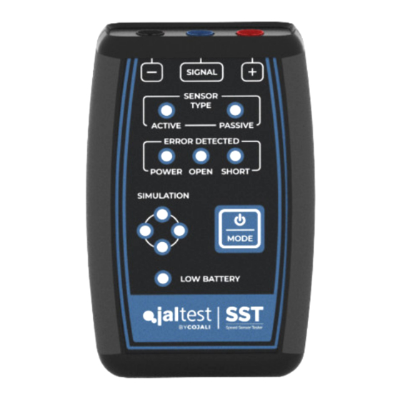
ECUs to which they are connected. Jaltest SST has a button that allows the user to interact with the device to select the operating mode. The user, through a lighting panel of LED devices, can easily detect possible errors without the need to carry out difficult and complex tests. -
Page 5: Equipment Composition
English 1.3 EQUIPMENT COMPOSITION Jaltest SST is made up of an electronic device with operating interface with a button and LEDs, as well as a complete kit of cables and multipins that allow connection in the sensor and ECU connector pins. It has a 9 V alkaline battery type 6LR61. -
Page 6: Functions And Connections
Connections: Warning: To prevent possible errors, ensure that you have selected the correct mode for the desired connection. To connect Jaltest SST device to sensor or ECU, the multipin kit should be used as follows: Connect to ACTIVE sensor Connect to PASSIVE sensor... -
Page 7: Procedures
In this mode, the speed sensor is disconnected from the ECU and connected to the Jaltest SST device to be able to check it in isolation. By turning the component whose sensor the user wants to check, they can determine if the sensor generates a correct signal. -
Page 8: Simulation Mode
In this mode, the speed sensor is disconnected from the ECU and connected to the Jaltest SST device to be able to check it in isolation. By turning the component whose sensor the user wants to check, they can determine if the sensor generates a correct signal. - Page 9 LED of the errors that may appear. Note: In case that the short circuit error appears in the Jaltest SST device, it can be removed once step 3 is being carried out with just a short press of the selection button of the Mode.
- Page 10 In this mode, the Jaltest SST device generates a signal that simulates the behaviour of an active sensor. When connecting the Jaltest SST device to the ECU and with the help of a diagnosis device that shows the speed read by the ECU, the user will be able to detect errors in the wiring or in the control unit itself.
-
Page 11: Connection Diagrams
English Error check: ٚ The power supply error LED lights up: There is an error in the sensor power su- pply cable or the ECU does not provide the appropriate voltage for this cable or the ECU connector in which we have connected to is not for a passive speed sensor. - Page 12 English IMAGE 2 Read mode - Passive Sensor PASSIVE SENSOR MULTIPINS SIGNAL IMAGE 3 Simulation mode - Active sensor MULTIPINS SIGNAL SIGNAL...
- Page 13 English IMAGE 4 Simulation mode - Passive Sensor Note: In most cases, the «+» multipin must be connected to the pin with the highest voltage concerning the ECU ground and the «SIGNAL» multipin to the lowest voltage pin concerning the ECU ground. MULTIPINS SIGNAL IMAGE 5...
-
Page 14: Technical Data
English 4 Technical data ٚ Device size: 118 x 79 x 32 mm ٚ Case size: 245 x 205 x 45 mm ٚ Device weight: ~ 180 g ٚ Complete case weight: ~ 700 g ٚ As security measure and in order to avoid the total battery discharge, the Jaltest SST device automatically disconnects the power supply of the electronic... - Page 15 2020 V.1 EN...

Need help?
Do you have a question about the Jaltest SST and is the answer not in the manual?
Questions and answers