Advertisement
Quick Links
22°
22°
22°
22°
22°
22°
GW
PC in internal network
FIGURE 1 structure of wireless sensor network
The mesh structure of the wireless network improves network reliability. The signal has multiple routes, from
which the system automatically selects the strongest. The larger the number of routers in the coverage area,
the more routing options the signal has. One wireless base station can monitor data from up to 100 sensors.
Base station connections:
– Direct connection to base station with browser. (over the Internet/locally)
– Ounet connection directly from the base station. (over the Internet)
– local Modbus RTU connection.
(Connections can be utilised simultaneously)
Initial engineering in network construction:
•
Building structures are crucial in network engineering. Metal structures weaken the signal, which is also the case for
lift wells, electrical power centres, fire doors, etc.
•
Old concrete buildings are easier in regard to networks than buildings constructed in the 2010s, where the amount
of steel in the structures is higher.
•
From the base station, the network should be built by first finding a suitable "backbone" for the network and applying
the operating voltage to the sensors, so that they will act as routing elements in the network. See FIGURE 1.
•
Once the network is operational in this regard, battery-operated sensors are placed as part of the network.
•
The positioning of room sensors must take into account that the sensor should never be exposed to direct sunlight.
It must also be ensured that no other external sources of heat affect the sensor, such as refrigerators, television sets,
ventilation windows, water radiators, etc.
•
It is often the easiest way to place the base station to the same space with the automation substation (heat distribu-
tion room, AHU room), but due to the weak 3G signal the optimal location can also be in the other parts of the build-
ing. Centrally selected location for the base station can improve the functionality of the sensor network, because
more sensors can be directly connected to the base station without routers.
•
It is able to select external antenna to the base station which improves reception of the sensor network when need-
ed to achieve better signal levels.
•
The base station requires a separate housing, e.g. K118 which also includes the needed power supply. (must be ap-
plied when certain IP protection class is needed)
Internet / Ounet
22°
22°
22°
= Base station
Internet
connection
= Routing wireless sensor
= Wireless sensor
Wireless sensor system
General description
The wireless Ouman sensor system
enables a quick and easy reading of
precise room temperature data in a
building without the laborious laying of
cables and drilling of walls. The sensor
system comprises a base station, sen-
sors that act as routers and are con-
nected to the mains, and battery-op-
erated wireless sensors. A predefined
register list makes it easy to connect
the wireless sensors to a SCADA sys-
tem. In the event of failure, a damaged
sensor can be replaced without chang-
ing the register list. This makes the
installation of the replacement sensor
quicker and easier.
Advertisement

Subscribe to Our Youtube Channel
Related Manuals for OUMAN WL-Base

Summary of Contents for OUMAN WL-Base
- Page 1 Wireless sensor system Internet / Ounet General description The wireless Ouman sensor system enables a quick and easy reading of 22° 22° 22° precise room temperature data in a building without the laborious laying of cables and drilling of walls. The sensor system comprises a base station, sen- 22°...
- Page 2 6. When the LINK light remains green, the base station has suc- cessfully been connected to the Ouman ACCESS network. 7. If you have a QR reader, read the QR code of the base station label. In other case, enter the label’ s website address in your Web browser.
- Page 3 Commissioning the wireless base station without the Web browser interface 1. Connect the antenna (or the extra antenna with an extension cord) to the antenna connection of the base station. Do not de- tach or attach the antenna when the base station is live! 2.
-
Page 4: Sensor Configuration
Commissioning the sensors 1. Commission the base station before commissioning the sen- sors (see pp. 2–3). 2. Open the room sensor's cover and install the batteries or switch on the operating voltage if you intend to make the sen- sor a routing sensor. Do not put batteries in the sensor if you apply the operating voltage to the sensor! 3. - Page 5 AUX connection of wireless room sensor In the wireless sensor or routing sensor, it is possible to connect an external temperature measurement, digital input, status data or 0–10 VDC transmitter measurement by using the AUX con- nection. AUX connection in temperature measurement 1.
- Page 6 Web UI, Figure 2 4. You can also enter the installation mode through the Web UI by clicking this icon. To exit the installation mode, click the icon. Or, if you do not do that, an automatic exit will take place after 90 minutes.
-
Page 7: Base Station Configuration
Web UI, Figure 3 Base station configuration OK button – In the installation mode, the sensor sampling interval is 10 seconds by default. When there are 15 or more sensors in “join mode”, the sampling interval will slow down the device. When you press “OK”, the sensor’ s sampling inter- val will change to two minutes, which will accelerate the device. - Page 8 Base station sensor settings...
- Page 9 Selections of average calculation Go to the “Sensor selection” tab or the sensor-specific settings to select the measurements to be included in the calculation. Avg calculation time span: The calculation can be performed as sliding for a specific period. If the value is 0, the value is an “on- line”...
- Page 10 Base station configuration...
- Page 11 The base station will automatically retrieve the network settings once the device is connected to the network and the power is switched on. xx.xx.xx.xx xx.xx.xx.xx xx.xx.xx.xx xx.xx.xx.xx xx.xx.xx.xx You can open the function menu by clicking the three dot icon in the upper right corner of the Web UI.
-
Page 12: Technical Details
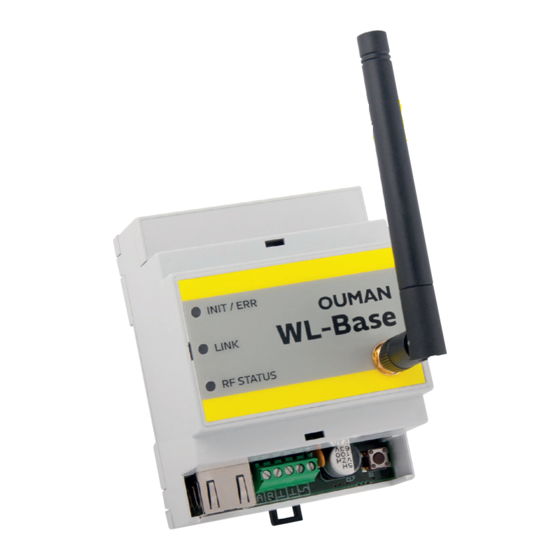
– Sensor placed in a weak field measurement, 0–10 V transmitter measure- (Occasionally dropped out from the network) ment or contact terminal information. External power source (operated as routing 5 VDC temperature sensor) Dimensions 80 x 85 x 30 mm Installation Surface installation OUMAN OY www.ouman.fi...
Need help?
Do you have a question about the WL-Base and is the answer not in the manual?
Questions and answers