Advertisement
Quick Links
P r o d u c t S p e c i f i c a t i o n
!
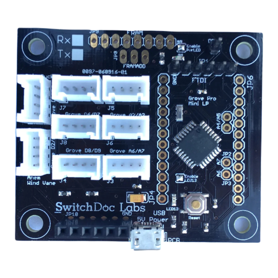
The Grove Pro Mini LP is an Arduino compatible
computer board with a full set of Grove devices. It is
designed for use in Low Power applications such as
battery and Solar Power applications. The Grove
connectors allow quick and solderless prototyping of
IOT applications.
•
Full Compatible Pinout with the Arduino Pro Mini
•
8 Different Grove Connectors
•
Allows you to build circuits with no soldering
Introduction
______________________________________________________________________________________
SwitchDoc Labs, LLC, 20089 E Glenbrook Ave,, Liberty Lake, Washington 99016 - sales@switchdoc.com
The Arduino family of processors is a fabulous prototyping and building
system for Makers. The combination of the Arduino IDE with its thousands
of available drivers for sensors and the ATMega line of processors have
spawned a tremendous burst of creativity around the world.
We redesigned the Arduino Pro Mini LP board to be very low power. We
removed the regulating power supply, modified the circuit to run the
processor at 8MHz and provided 3.3V and 5V compatibility.
Version 3.0 - Page
Grove Pro Mini LP
Features and Benefits:
• 8MHz Low Power Processor
• 12 GPIO pins
• 1 Hardware Serial Port
• 8 - 10 Bit Analog ports
• I2C Interface
• Reset Pin
• Multiple SoftSerial Ports
• SPI Interface
• Really Low Power Usage (for Solar applications!)
• Grove Connector Compatibility for IOT
Prototyping
• ATmega328P Processor
• Arduino Pro Mini Compatible Pinout
• Under 1mA sleep current
• DS3231 Real Time Clock Included
• 3.3V - 5V
• Arduino IDE Compatible
• Thousands of drivers available
• Compatible with Hundreds of Grove Sensors
• Low Cost
• Full Test Code Supplied
• Quantity Discounts Available
• Immediate Availability
1
of
19
0097-060916-01
Advertisement

Summary of Contents for SwitchDoc Labs Grove Pro Mini LP
- Page 1 We redesigned the Arduino Pro Mini LP board to be very low power. We removed the regulating power supply, modified the circuit to run the processor at 8MHz and provided 3.3V and 5V compatibility. ______________________________________________________________________________________ SwitchDoc Labs, LLC, 20089 E Glenbrook Ave,, Liberty Lake, Washington 99016 - sales@switchdoc.com Version 3.0 - Page...
- Page 2 Each Grove Pro Mini LP Board ships with a plug-in DS3231 highly accurate RTC (Real Time Clock) that can be used to wake the Grove Pro Mini LP up at regular intervals or even on specific dates! (Software provided). Combine the Grove Pro Mini LP with a SunAir or SunAirPlus board to create a solar powered IOT device Additional code and examples on www.switchdoc.com on the Grove Pro Mini LP Product Page...
- Page 3 The Grove Pro Mini can be powered with an FTDI cable or breakout board connected to its six pin header, or with a regulated 3.3V or 5V supply on the VDD pin. On the Grove Pro Mini LP, the RAW pin is not connected.
- Page 4 Communication The Grove Pro Mini LP has a number of facilities for communicating with a computer, another Arduino, or other microcontrollers. The ATmega328 provides UART TTL serial communication, which is available on digital pins 0 (RX) and 1 (TX). The Arduino software includes a serial monitor which allows simple textual data to be sent to and from the Arduino board via a USB connection.
- Page 5 Software Software and drivers for Grove Pro Mini LP boards for the Raspberry Pi and the Arduino can be located on the SwitchDoc Labs Grove Pro Mini LP product page (www.switchdoc.com). The Pro Mini LP can be programmed as any Arduino compatible device through the Arduino IDE (select Arduino Pro or Pro Mini from Board Manager and then ATmega328 (3.3V, 8Mhz).
- Page 6 Additionally, the RST pin is monitored as a pushbutton input for generating a µP reset. Note that the 32KHz line and the NINT/SQW Line are connected to D3/D2 on the Grove Pro Mini LP respectively. This allows you to use the DS3231 as a timer and alarm source of interrupts.
- Page 7 Idd* <5 *Grove Pro Mini LP Power Consumption depends on what other devices you have added to the board. Actual Current Measurement Results. The tall spikes are when the radio transmitter is on (for a very short time - we still end up with <...
- Page 8 Physical dimensions of board: 50mm x 50mm x 10.0mm(max). Mounting holes inset 3.2mm x 3.2mm from each corner to center of hole. Diameter of hole 3mm. ______________________________________________________________________________________ SwitchDoc Labs, LLC, 20089 E Glenbrook Ave,, Liberty Lake, Washington 99016 - sales@switchdoc.com Version 3.0 - Page...
- Page 9 With the large selection of Grove I2C devices available, we decided to include a Grove connector on all our future I2C boards. The white connectors on the Grove Pro Mini LP board picture at the top are Grove connectors for easy, non-soldered connections to the I2C bus and for data inputs.
- Page 10 What Grove Connectors Are On The Grove Pro Mini LP? There are two types of Grove Connectors on the Grove Pro Mini LP board. There is two Grove I2C connectors, three Grove Digital connectors, two Grove Analog connectors and one Mixed Digital/Analog connector.
- Page 11 Digital I/O pins to implement the I2C bus. The pins on the Raspberry Pi and Arduino are special with hardware support for the I2C bus. The ESP8266 is purely software. Note that the Grove I2C Connectors on the Grove Pro Mini LP is a 5V or 3.3V (depending on what VDD is connected to) I2C connector.
- Page 12 Grove I2C Pin 1 I2C Clock Pin 2 I2C Data Pin 3 Power for Grove Module (5V or 3.3V) Pin 4 Ground ______________________________________________________________________________________ SwitchDoc Labs, LLC, 20089 E Glenbrook Ave,, Liberty Lake, Washington 99016 - sales@switchdoc.com Version 3.0 - Page...
- Page 13 This Connector can be used to connect up to a processor such as the Raspberry PI or to an I2C Hub expander. See articles and application notes on www.switchdoc.com. ______________________________________________________________________________________ SwitchDoc Labs, LLC, 20089 E Glenbrook Ave,, Liberty Lake, Washington 99016 - sales@switchdoc.com Version 3.0 - Page...
- Page 14 J4 - Grove Digital J4 - Grove Digital J4 - Grove Digital Pin 1 Digital I/O Pin 8 Pin 2 Digital I/O Pin 9 ______________________________________________________________________________________ SwitchDoc Labs, LLC, 20089 E Glenbrook Ave,, Liberty Lake, Washington 99016 - sales@switchdoc.com Version 3.0 - Page...
- Page 15 J2 - Grove Digital / Analog Pin 1 Digital I/O Pin 2 Pin 2 Analog A1 Input Pin 3 Power for Grove Module Pin 4 Ground ______________________________________________________________________________________ SwitchDoc Labs, LLC, 20089 E Glenbrook Ave,, Liberty Lake, Washington 99016 - sales@switchdoc.com Version 3.0 - Page...
- Page 16 Jumper Pin Functions D5 Pin - Connects to D5 on the Grove Pro Mini LP Board This pin is generally used to connect to the enable pin on the Serial RF Pro board to reduce power usage. It is a general use pin connected to D5.
- Page 17 JP1, JP4 and JP6 are given below in the Arduino Pro Mini diagram. Note that RAW is a no connect on the Grove Pro Mini LP Board as there is no power regulator on the board. You must supply regulated VDD through the VDD pin (VCC pin on the diagram) or through the USB power port on the board.
- Page 18 This is included with the Weather Board Board. When plugging the DS321 module into the Weather Board make sure to align the GND pins. Battery side towards the center of the board. ______________________________________________________________________________________ SwitchDoc Labs, LLC, 20089 E Glenbrook Ave,, Liberty Lake, Washington 99016 - sales@switchdoc.com Version 3.0 - Page...
- Page 19 JP10 / 1 32kHz Output. When enabled this is connected to D2 on the Grove Pro Mini LP. It allows you to use this output as an Interrupt source to the Pro Mini LP. You must turn on the internal Arduino pullup on D2 to use.
Need help?
Do you have a question about the Grove Pro Mini LP and is the answer not in the manual?
Questions and answers