
Summary of Contents for Ochsner OTE 3
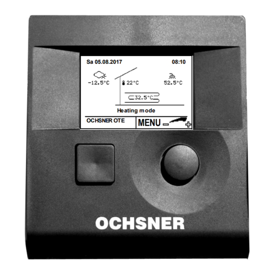
- Page 1 Operating Instructions Heat Pump Control OTE 3 / OTE 4 Sa 05.08.2017 08:10 Heating m ode MENU OCHSNER OTE Heat Pump Control Heating/Cooling/Hot Water BA_OTE 3+4_Endkunde_EN_V03_20170726.docx Page 1 of 52...
-
Page 2: Table Of Contents
Contents General ........3 Heat pump ........ 27 Proper use ........3 Temperature image ....28 CE-Labelling ........ 3 Operational data ......28 Relay test ........29 Safety instructions ..... 4 De-icing start manual ....30 Description ......... 5 Auxiliary heater ......31 System OTE ......... -
Page 3: General
The control has been designed so that it The following manual is intended to be a can be deployed in many different sys- support for the operation of OCHSNER tems. It is thus possible that not all the heat pumps which are equipped with the functions described here are used in your OCHSNER Tronic Easy ©... -
Page 4: Safety Instructions
OCHSNER accepts no liability for as the terminal strips could be possible damage due to im- live (danger of contact with live proper use. -
Page 5: Description
Sa 05.08.2017 08:10 Heating m ode MENU OCHSNER OTE Fig. 2: Basic control panel Fig. 1: OTE control in the heat pump 3.2 Further control elements A control unit can regulate the following Further control elements are the room system circuits/heat generators. -
Page 6: System Operation
Date Time of day Sa 05.08.2017 08:10 Outside tem- Hot water tem- perature perature Heating m ode MENU OCHSNER OTE Heat pump opera- System flow tempera- tional condition ture (e.g.: buffer top) Button B one step back Button A (ESC) -
Page 7: Menus
Incorrect changes to settings in Example main menu: password protected levels can lead to damage to the system! OCHSNER accepts no liability for Main menu HEATING CIRCUIT 1 this! HEATING CIRCUIT 2 HOT WATER HEAT PUMP... -
Page 8: Heating/Cooling (Heating Circuits)
(which can measure the current room temperature in this heating circuit), the current room temperature can also be additionally used for calculating the set flow temperature. If you wish to use this function, please contact your OCHSNER system partner. BA_OTE 3+4_Endkunde_EN_V03_20170726.docx Page 8 of 52... -
Page 9: Operation Selection Heating Circuit
HOT WATER display > the main menu appears HEAT PUMP Heating m ode MENU ENTER OCHSNER OTE Select the Heating Circuit by turning the ad- justment knob and confirm by pressing the knob. HEATING CIRCUIT 1 HEATING CIRCUIT 1 Operation mode... -
Page 10: Temperature Image
5.4 Temperature image The temperature image gives an overview of the condition and temperatures of direct heating circuits and mixing circuits. Outside temperature (TA) Room temperature (TI) (only if there is a room unit) Heating circuit pump (HKP) ON-OFF HEATING CIRCUIT 1 Flow temperature Depending on the type of system, the measured val- ue will be taken from one of the following sensors:... -
Page 11: Relay Test
Press the adjustment knob in the main HEAT PUMP Heating m ode display > the main menu appears MENU ENTER OCHSNER OTE Select the desired menu by turning the adjustment knob and confirm by pressing the knob. HEATING CIRCUIT 1 HEATING CIRCUIT 1... -
Page 12: Adjusting The Heating Curve
5.7 Adjusting the heating curve For weather dependent heating controls, the current set flow temperature is deduced by means of the current outside temperature. The heating curve is also used. The heating curve is adjusted using 3 parameters. Heating starts only when the mean outside temper- ature in the past 10 h (standard setting) is lower than the set heating limit (see Section 0) Parameter Description... - Page 13 Record the adjustments in the Table: Heating curve Comments Date 03-001 03-013 Table 1: adjust heating curve Flow temperature heating circuit (VLT) [°C] Design supply temperature (03-013) Base point temperature heat- ing curve (03-001) Outside temperature [°C] Fig. 9: Heating curve correction a) Modified heating curve when the base point temperature (03-001) is set higher b) Basic heating curve set by the heating engineer during commissioning c) Modified heating curve when the base point temperature (03-013) is set lower...
-
Page 14: Set Heating Curve
Select the Heating Circuit by turning the HEAT PUMP Heating m ode MENU ENTER adjustment knob and confirm by pressing OCHSNER OTE the knob. > the temperature image for the heating circuit appears. In heating circuit temperature image, se- HEATING CIRCUIT 1 HEATING CIRCUIT 1... -
Page 15: Cooling Curve
Incorrect cooling curve settings can cause damage to the system (condense wa- ter build up). OCHSNER accepts no liability for this! Change the cooling curve settings only after consulting your contractual partner! BA_OTE 3+4_Endkunde_EN_V03_20170726.docx... -
Page 16: Setting The Cooling Curve
Select the Cooling circuit by turning the HEAT PUMP Heating m ode adjustment knob and confirm by pressing MENU ENTER OCHSNER OTE the knob. > the temperature image for the heating circuit appears. In heating circuit temperature image, se- HEATING CIRCUIT 2 HEATING CIRCUIT 2... -
Page 17: Set Temperature For Heating
HEAT PUMP Select the Heating Circuit by turning the ad- Heating m ode MENU ENTER OCHSNER OTE justment knob and confirm by pressing the knob. > the temperature image for the heat- ing circuit appears. In heating circuit temperature image, select... -
Page 18: Setting The Cooling Limit
Select the Heating Circuit by turning the HEAT PUMP Heating m ode adjustment knob and confirm by pressing MENU ENTER OCHSNER OTE the knob. > the temperature image for the heating circuit appears. In heating circuit temperature image, se- HEATING CIRCUIT 1 HEATING CIRCUIT 1... -
Page 19: Set Temperature For Cooling
> the main menu appears HEAT PUMP Heating m ode MENU ENTER OCHSNER OTE Select the Heating Circuit by turning the adjustment knob and confirm by pressing the knob. > the temperature image for the HEATING CIRCUIT 1 HEATING CIRCUIT 1 heating circuit appears. -
Page 20: Set Temperature Manual Operation
Select the Heating Circuit by turning the HEAT PUMP Heating m ode adjustment knob and confirm by pressing MENU ENTER OCHSNER OTE the knob. > the temperature image for the heating circuit appears. All heating circuits are always displayed in the main menu. HEATING CIRCUIT 1... -
Page 21: Hot Water Circuit
HEAT PUMP Heating m ode Select the Hot Water Circuit by turning the MENU ENTER OCHSNER OTE adjustment knob and confirm by pressing the knob. > the temperature image for the hot water circuit appears. In hot water circuit temperature image,... -
Page 22: Temperature Image
6.2 Temperature image The hot water circuit temperature image gives an overview of the conditions and temper- atures. HOT WATER Hot water charging via heat pump ON-OFF Hot water temperature (TB) Hot water charging via electrical rod ON-OFF MENU 6.3 Operational data The operational data can be seen in the hot water menu: Operational data Description... -
Page 23: Set Hot Water Temperature
HOT WATER display > the main menu appears HEAT PUMP Heating m ode MENU ENTER OCHSNER OTE 2. Select the Hot water circuit in the main menu 3. In hot water circuit temperature image, HOT WATER HOT WATER select the hot water circuit menu by Operation mode pressing the adjustment knob. -
Page 24: Time Program
7 Time program 7.1 Settings procedure selected weekday Owner's name HEATING CIRCUIT 1 Set-back period Change period 00:00 (reduced set value: Normal period economy operation Room temperature night/set-back, heating ENTER limit set back, ...) Fig. 11: Time program display Changing the time program: Example: Set-back period setting from 20:00 to 5:00. -
Page 25: Time Program For Heating
Select the Heating Circuit by turning the HEAT PUMP Heating m ode adjustment knob and confirm by pressing MENU ENTER OCHSNER OTE the knob. > the temperature image for the heating circuit appears. In heating circuit temperature image, se- HEATING CIRCUIT 1 HEATING CIRCUIT 1... -
Page 26: Time Program For Hot Water
Select the Hot Water Circuit by turning the HEAT PUMP Heating m ode adjustment knob and confirm by pressing MENU ENTER OCHSNER OTE the knob. > the temperature image for the hot water circuit appears. In hot water temperature image, select the HOT WATER HOT WATER... -
Page 27: Heat Pump
Select the heat pump by turning the ad- HEAT PUMP Heating m ode MENU ENTER OCHSNER OTE justment knob and confirm by pressing the knob. > the temperature image for the heat pump appears. In heat pump temperature image, select... -
Page 28: Temperature Image
8.1 Temperature image HEAT PUMP Heat generator pump (WEP) ON-OFF Heat source input (TQE) Heat pump flow (TWV) Heat pump return (TWR) Heat source output (TQA) Heat pump ON-OFF MENU 8.2 Operational data The operational data can be seen in the heat pump menu: Operational data Description 02-053 Status heat generator... -
Page 29: Relay Test
temp.) 00-008 TWR temperature (HP Heat pump return temperature (sensor TWR) return temp.) 00-070 TQA heat source output Heat source outlet temperature (sensor TQA), for temp. Air/Water heat pumps - evaporator temperature 2 00-071 TQE heat source input Heat source input temperature (sensor TQE), for temp. -
Page 30: Icing Start Manual
Select the heat pump by turning the ad- HEAT PUMP Heating m ode MENU ENTER justment knob and confirm by pressing the OCHSNER OTE knob. > the temperature image for the heat pump appears. In heat pump temperature image, select HEAT PUMP HEAT PUMP... -
Page 31: Auxiliary Heater
Select the auxiliary heater by turning the HEAT GENERATOR 2 Heating m ode adjustment knob and confirm by pressing MENU ENTER OCHSNER OTE the knob. > the temperature image for the auxiliary heater appears. In auxiliary heater temperature image, se- HEAT GENERATOR 2 HEAT GENERATOR 2... -
Page 32: Temperature Image
9.1 Temperature image The auxiliary heater temperature image gives an overview of the conditions and tempera- tures. HEAT GENERATOR 2 Auxiliary heater flow temperature (TPO) Auxiliary heater ON-OFF MENU 9.2 Operational data Operational data Description 02-053 Status heat generator 1 = Heating mode Auxiliary heater switched on 2 = Lead time heating mode Switch off via utility... -
Page 33: Heat Distribution / Heat Manager
11 Cascade manager The cascade manager is necessary when several heat pumps are used in a heating system (cascading). If required, please contact the OCHSNER customer service or your nearest OCHSNER system partner BA_OTE 3+4_Endkunde_EN_V03_20170726.docx Page 33 of 52... -
Page 34: Photovoltaic-Energy Own Consumption
12 Photovoltaic-Energy own consumption You can ideally use available energy from your photovoltaic system (if installed) with your OCHSNER heat pump. For this you need a switching contact of the photovoltaic system, which gives the heat pump control OTE the signal "energy available”. -
Page 35: Smart-Grid-Function (To Bwp)
(if this is set correspondingly in your system) takes place). If you wish to use this function, please contact your OCHSNER customer service or your nearest OCHSNER system partner. -
Page 36: Building Management
0-10V DC signal and a switching contact for heating/cooling. The control can furthermore send certain operational conditions to the building management system (e.g.: Heat pump running, heat pump in cooling operation. If you wish to use this function, please contact your nearest OCHSNER system partner. 15 Service-Report 15.1 Setting date and time Settings procedure: Sa 05.08.2017... -
Page 37: Set Master Data
CASCADE MANAGER Select the Service Report by turning the SERVICE REPORT Heating m ode MENU ENTER OCHSNER OTE adjustment knob and confirm by pressing the knob. By turning the adjustment knob, select Master Data in the Service Report menu SERVICE REPORT SERVICE REPORT and confirm this by pressing the knob. -
Page 38: Floor Screed Heating Programme
15.3 Floor screed heating programme 1. Starting the floor screed heating programme The heating circuit pump is switched on at the start. The flow temperature is read after 5 minutes. The measured value is stored as the start and end temperature set value. - Page 39 The settings for set value increase or equilibrium phase must be adjusted by a professional partner after consultation with the floor screed professional! In- correct settings can lead to damage to the floor screed. OCHSNER accepts no li- ability for this!
-
Page 40: Start The Programme
Select the Service Report by turning the SERVICE REPORT Heating m ode MENU ENTER adjustment knob and confirm by pressing OCHSNER OTE the knob. By turning the adjustment knob, select Settings in the Service Report menu and SERVICE REPORT SERVICE REPORT confirm this by pressing the knob. -
Page 41: Error Reports
16 Error reports Error reports will only be displayed on the master control unit. Via the ESC knob, "INFO" and an error text appear (see Fig. 13). Sa 20.07.2013 15:41 INFO: When “INFO” is displayed, the controller created an error report. Em ergency m ode econom y MENU INFO... -
Page 42: Alarm
16.1 ALARM The report ALARM appears when a sensor is defect. (Exception: Breakage of safety- related sensors Report "ERROR" / "LOCK" A substitute value is made. The heat pump continues in emergency mode. 16.2 Procedure by ALARM Contact your contractual partner and arrange for the sensor to be replaced. Example hot water sensor defect: Press the ESC knob in the main display >... -
Page 43: Error
> repeated pressing of the ESC knob returns to main display. Remedying the ERROR reports may only be carried out by OCHSNER authorised installers! Before beginning work on the heat pump, it must be switched off on all poles from the power supply and protected against switching back on! Incor- rect changes to settings by third parties will delete all warranty and guarantee claims. -
Page 44: Error Table
Check the hydraulics Heat source insufficient, not enough re- Er 37: Low pressure frigerant, expansion valve Check the refrigerant circuit (OCHSNER) Expansion valve, insufficient refrigerant, Er 38: Hot gas set value too high Check the refrigerant circuit (OCHSNER) Motor protection relay, Phase er-... - Page 45 Possible cause/ remedy code Er 46: TSG sensor defect Replace sensor Insufficient de-icing energy Er 47: De-icing malfunction Evaporator/Sensor Check the refrigerant circuit (OCHSNER) Er 48: TQE sen- Replace sensor sor/evaporator 1 defect Er 49: TQA sen- Replace sensor sor/evaporator 2 defect...
- Page 46 Er 91: Flow rate in heat use pump defect, valve closed/air in sys- system tem, check hydraulics Er 90: Overheating Check the refrigerant circuit (OCHSNER) Er 98: Electrical heating Check the heat pump operation selec- rod is only heat generator! tion (see Section8)
-
Page 47: Procedure By Blocking
16.6 BLOCKING In "BLOCKING" cases, the system changes to "emergency mode economy". The heat pump is switched off. The system is controlled at reduced temperatures (heating and warm water) and the additional heat generators (electro auxiliary, furnace) take over the heating (if installed). -
Page 48: Heat Meter
17 Heat meter The OTE control offers the possibility of recording the amount of heat the heat pump gives off. The recording takes place using the classic heat meter method. The temperature differential of the heat pump is continuously measured and the amount of heat calculated with the flow rate. - Page 49 Select the heat pump by turning the ad- HEAT PUMP Heating m ode justment knob and confirm by pressing MENU ENTER OCHSNER OTE the knob. > the temperature image for the auxiliary heater appears. In heat pump temperature image, select HEAT PUMP HEAT PUMP...
-
Page 50: Annex
18 Annex 18.1 Technical Data Control Description Data OTE3 (SE6024WPC) Data OTE4 (SE6034WPC) Operational voltage ~ 230 V (AC) ± 10%, 50 Hz Current draw stand-by < 11W Maximum current draw max. 16 W max. 15W Measurement circuit voltage Ambient temperature in operation 0°C to 50°C Ambient temperature storage -20°C to 60°C... - Page 51 Notes: BA_OTE 3+4_Endkunde_EN_V03_20170726.docx Page 51 of 52...
- Page 52 Address: ......................................................Tel.: ............................Service engineer: .............................. OCHSNER OCHSNER OCHSNER Wärmepumpen GmbH Austria Ochsner Wärmepumpen GmbH Germany Wärmepumpen GmbH Switzerland (Company book) D-60314 Frankfurt a.M. CH-8001 Zürich Krackowizerstraße 4 Riederhofstraße 27 Uraniastrasse 18 A-4020 Linz Hotline for System partner: +49 (0) 1805832840 Customer service hotline +41 (0) 800 100 kontakt@ochsner.at...