
Summary of Contents for FiberHome AN5121-4GP
- Page 1 An Expert in Optical Communications User Manual AN5121-4GP PON Optical Network Unit Version: A Code: MN000001901 Date: September 2014 FiberHome Telecommunication Technologies Co., Ltd.
- Page 2 Version Version Description Initial version. are trademarks of FiberHome Telecommunication Technologies Co., Ltd. (Hereinafter referred to as FiberHome) All brand names and product names used in this document are used for identification purposes only and are trademarks or registered trademarks of their respective holders.
-
Page 3: Table Of Contents
Contents 1 Safety Precautions ............. 1 2 Product Introduction............3 2.1 Product Overview ............3 2.2 Network Application............6 2.3 Technical Specifications..........7 3 Product Appearance ............10 3.1 Appearance..............10 3.2 Indicator LED Description ..........13 3.3 Interface Description.............15 3.3.1 Interfaces of the Waterproof Shell .......15 3.3.2 Interface of the Equipment........15 3.3.3 Introduction to the Pole Components ....17 3.3.4 Introduction to the Cabinet Components .....18... - Page 4 4.4.2 Wall Mounting Mode ...........38 4.4.3 Securing the Equipment ........41 4.4.4 Connecting Wires and Cables......42 4.5 Cabinet Mounting Mode..........42 4.5.1 Installation Flow Chart ........42 4.5.2 Installing the Mounting Ears........43 4.5.3 Cabinet Mounting Mode........44 4.5.4 Connecting Wires and Cables......46 4.6 Post-installation Inspection ...........47 5 FAQ ..................
-
Page 5: Safety Precautions
1 Safety Precautions 1 Safety Precautions Large-power laser is dangerous to human body, especially to eyes. Do not face the pigtail fiber of the optical transmitter or the end of the fiber cable connector to eyes. Power sockets with too heavy load or damaged cables and connectors may cause electric shock or fire. - Page 6 1 Safety Precautions Install the silicon rubber waterproof band into the recess on the lower cover of the device case to ensure water proofing.
-
Page 7: Product Introduction
The following introduces the functions, network applications and technical specifications of the AN5121-4GP. 2.1 Product Overview The AN5121-4GP is a GPON FTTB / FTTV type remote terminal specially developed for the network access at the outdoor environment, the video monitoring, the Wi-Fi hot spot deployment, etc. - Page 8 2 Product Introduction Function The AN5121-4GP supports the following functions: Basic PON functions: Uses the GPON connection in the uplink direction, meeting the ITU-T G.984 standard. Supports multiple authentication modes, including the physical ID authentication, the password authentication, and the logical SN authentication.
- Page 9 Supports the local WEB network management function. The operators can log in via the user LAN port to view the information of the AN5121-4GP and modify the logical SN and password of the ONU. Supports managing the ONU remotely in the Telnet mode, and users can view the ONU status information and print the debug information.
-
Page 10: Network Application
Product Model AN5121-4GP with four GE interfaces. 2.2 Network Application The AN5121-4GP is mainly used in the FTTB / FTTV type access scenarios, providing the power supply for some equipment sets and the access of the data services for users. -
Page 11: Technical Specifications
2 Product Introduction Figure 2.1 The AN5121-4GP Application Network 2.3 Technical Specifications The technical specifications of the AN5121-4GP are listed in Table 2.1. Table 2.1 The AN5121-4GP Technical Specifications Type Item Description Supports the IEEE 802.1Q / 802.1P Service VLANs and VLAN-based selective QinQ. - Page 12 2 Product Introduction Table 2.1 The AN5121-4GP Technical Specifications (Continued) Type Item Description The capacity of the system MAC address MAC address table is 1K. Layer 2 line rate All ports support line rate forwarding. forwarding Supports eight priority queues at most.
- Page 13 2 Product Introduction Table 2.1 The AN5121-4GP Technical Specifications (Continued) Type Item Description Power Full load <130W consump- tion Empty load <10W parameters Operating to 55 temperature Environ- Storage ment to 125 temperature parameters Environmental 0% to 80% (no condensation).
-
Page 14: Product Appearance
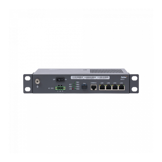
The following introduces the appearance of the AN5121-4GP and the waterproof shell for it. The AN5121-4GP The overall appearance of the AN5121-4GP is shown in Figure 3.1. Figure 3.1 The Appearance of the AN5121-4GP The panel of the AN5121-4GP is shown in Figure 3.2. - Page 15 Figure 3.2 The AN5121-4GP Panel Waterproof Shell The waterproof shell can be used together with the AN5121-4GP. Its top internal side is equipped with the waterproof bumper case, which can prevent the rain from entering the shell via the gaps. The appearance of the waterproof shell is shown in Figure 3.3.
- Page 16 3 Product Appearance (1) Wiring hole (2) Earth ground (3) Cable fixing (optional) component (optional) component (optional) Figure 3.4 Internal Structure of the Waterproof Shell...
-
Page 17: Indicator Led Description
AN5121-4GP to the external. 3.2 Indicator LED Description The AN5121-4GP has multiple types of indicator LEDs on it. Except for the four indicator LEDs (ACT, PSE, PON, and LOS), the link status and duplex status indicator LEDs are located beside each LAN port. - Page 18 3 Product Appearance Table 3.2 Description on Indicator LEDs of the AN5121-4GP (Continued) Silk- Meaning Indicator LED Description screen Color Status Name The Rx optical power of the Optical PON port is too low. signal status indicator The Rx optical power of the PON port is normal.
-
Page 19: Interface Description
Network cable The network cable is led in or out of the (2), (3) wiring hole waterproof shell through these interfaces. 3.3.2 Interface of the Equipment The AN5121-4GP's interfaces are all located on the front panel, as shown in Figure 3.6. - Page 20 Description Earth ground Used for the earth grounding of the equipment. cable interface Power switch Used to switch on or off the AN5121-4GP. AC power Used to induct the 220 V AC power supply from the interface external. The uplink PON interface, complying with the ITU-T G.
-
Page 21: Introduction To The Pole Components
3 Product Appearance 3.3.3 Introduction to the Pole Components The pole components comprise the equipment base and clamp. The clamp is used to secure the equipment base on the wire pole. Figure 3.7 shows the equipment base. Figure 3.7 The Base Figure 3.8 shows the clamp. -
Page 22: Introduction To The Cabinet Components
3 Product Appearance 3.3.4 Introduction to the Cabinet Components The cabinet components include the two mounting ears used to secure the equipment in the cabinet, as shown in Figure 3.9 and Figure 3.10. Figure 3.9 The Mounting Ear on the Left Side of the Cabinet Figure 3.10 The Mounting Ear on the Right Side of the Cabinet... -
Page 23: Product Installation
4.1 Installation Preparation Before installing the AN5121-4GP, check whether the following conditions are met: The selected position is suitable for installing and operating the AN5121-4GP. For example, check whether the power cables and optical cables can be accessed. -
Page 24: Pole-Holding Mounting Mode
4 Product Installation 4.3 Pole-holding Mounting Mode 4.3.1 Installation Flow Chart The installation flow chart for the pole-holding mode is shown in Figure 4.1. -
Page 25: Pole Mounting Mode
4 Product Installation Figure 4.1 The Installation Flow Chart for the Pole-holding Mounting Mode 4.3.2 Pole Mounting Mode The following introduces how to secure the waterproof shell on the wire pole. - Page 26 4 Product Installation Tool Six point sockets Procedure Take out the equipment base and the clamp. Figure 4.2 shows the base and Figure 4.3 shows the clamp. Figure 4.2 The Base Figure 4.3 The Clamp Secure the equipment base onto the wire pole with the clamp, as shown in Figure 4.4, and fasten the clamp with the six point sockets.
- Page 27 4 Product Installation Figure 4.4 Securing the Equipment Base Hang the waterproof shell on the equipment base, as shown in Figure 4.5. Find the hooks on the back of the waterproof shell, as indicated by (1) of Figure 4.5, and the gourd shaped holes on the equipment base, as indicated by (2) of Figure 4.5.
-
Page 28: Securing The Equipment
Hanging the Waterproof Shell 4.3.3 Securing the Equipment Tool None Procedure Secure the AN5121-4GP in the waterproof shell, as illustrated in Figure 4.7. Find the mounting holes at the bottom of the AN5121-4GP and the hooks inside the waterproof shell. - Page 29 Figure 4.6. Figure 4.6 Installing the Sheet Metal Align the mounting holes at the bottom of the AN5121-4GP with the hooks inside the waterproof hook to hang the equipment on the waterproof shell.
-
Page 30: Connecting Wires And Cables
4 Product Installation (1) Mounting hole (2) Hook Figure 4.7 Securing the Equipment to the Waterproof Shell 4.3.4 Connecting Wires and Cables The following introduces how to connect the wires and cables for the equipment. - Page 31 4 Product Installation The wires and cables to be connected for the equipment include The earth ground cable, The power cable, The optical fiber, The network cable. Tip: Before leading the external wires and cables into the waterproof shell, you need to loosen the waterproof connector. After completing the layout of wires and cables, fasten the waterproof connector and seal the interface.
- Page 32 4 Product Installation Figure 4.8 Connecting the Cable for the Connector Post Connect the other end of the external earth ground cable to the external earth ground bar. Fix one end of the internal earth ground cable on the earth ground point of the earth ground component, as shown in Figure 4.10.
- Page 33 4 Product Installation Figure 4.9 Connection to the Earth Ground Point Insert the other end of the internal earth ground cable into the earth ground hole of the AN5121-4GP, as shown in of Figure 4.10.
- Page 34 4 Product Installation (1) Waterproof (2) Connector post (3) Earth ground point connector Figure 4.10 Connecting the Earth Ground Cable 4.3.4.2 Connecting the Power Cable The power cable is used to connect the external power and the AN5121-4GP.
- Page 35 4 Product Installation Tool None Procedure Loosen the waterproof connector on the wiring hole on the left side of the waterproof shell. Lead one end of the power cable into the equipment via the wiring hole on the left side of the waterproof shell, as shown in of Figure 4.11.
- Page 36 4 Product Installation (1) Waterproof connector Figure 4.11 Connecting the Power Cable...
- Page 37 4 Product Installation 4.3.4.3 Connecting the Optical Cable The optical cable is used to connect the equipment's optical interface and the external communication equipment. Tool Cutting pliers Procedure Loosen the waterproof connector on the wiring hole on the left side of the waterproof shell. Lead one end of the optical cable into the equipment via the wiring hole on the left side of the waterproof shell, as shown in of Figure 4.12.
- Page 38 4 Product Installation (1) Waterproof connector Figure 4.12 Connecting the Optical Cable Install the connector for the optical fiber of the optical cable entering the equipment. Connect the reinforced core of the optical cable to the earth ground component, as shown in Figure 4.13.
- Page 39 Figure 4.12. 4.3.4.4 Connecting the Network Cable The network cable is used to connect the external communication equipment and the AN5121-4GP. Tool A cross screwdriver Procedure Loosen the waterproof connectors on the two wiring holes at the right side of the waterproof shell.
- Page 40 4 Product Installation (1) Waterproof connector (2) Cable fixing component Figure 4.14 Connecting the Network Cable Lead the network cable through the cable fixing component.
-
Page 41: Wall Mounting Mode
4 Product Installation Insert the RJ-45 connector of the network cable into the AN5121-4GP's network interface, as shown in of Figure 4.14. 4.4 Wall Mounting Mode 4.4.1 Installation Flow Chart The installation flow for the wall mounting mode is shown in Figure... -
Page 42: Wall Mounting Mode
4 Product Installation Figure 4.15 The Installation Flow Chart for the Wall Mounting Mode 4.4.2 Wall Mounting Mode The following introduces how to mount the waterproof shell on the wall. - Page 43 4 Product Installation Tool An electric drill A hammer A cross screwdriver Procedure Take out the waterproof shell. Drill four holes on the wall with the electric drill. See Figure 4.16 for the positions and sizes of the holes.
- Page 44 4 Product Installation Figure 4.16 Positions and Sizes of the Holes Install the expansion sleeve in the holes prepared. Install the four screws on the bottom of the waterproof shell into the expansion sleeve, and fasten the screws to secure the shell, as illustrated in Figure 4.17.
-
Page 45: Securing The Equipment
4 Product Installation (1) Screw (2) Expansion sleeve Figure 4.17 Securing the Waterproof Shell 4.4.3 Securing the Equipment Secure the AN5121-4GP in the waterproof shell. Refer to Securing the Equipment for the operation procedures. -
Page 46: Connecting Wires And Cables
4 Product Installation 4.4.4 Connecting Wires and Cables The following introduces how to connect the wires and cables for the equipment. Refer to Connecting Wires and Cables for the procedures of connecting the wires and cables. 4.5 Cabinet Mounting Mode 4.5.1 Installation Flow Chart The installation flow chart for the cabinet mounting mode is shown in Figure 4.18. -
Page 47: Installing The Mounting Ears
4 Product Installation Figure 4.18 The Installation Flow Chart for the Cabinet Mounting Mode 4.5.2 Installing the Mounting Ears The following introduces how to install the mounting ears on the equipment. Tool A cross screwdriver... -
Page 48: Cabinet Mounting Mode
Figure 4.19. Figure 4.19 Installing the Mounting Ears 4.5.3 Cabinet Mounting Mode Prerequisite When the mounting ears and bent angle brackets are used, users can install the AN5121-4GP in a 19-inch cabinet. Tool A cross screwdriver... - Page 49 Align the screw holes on the mounting ears and bent angle brackets on both sides of the AN5121-4GP. Push the mounting ears and bent angle brackets slowly toward the floating nuts until they touch closely. Then insert the screws into the screw holes on the floating nuts and tighten them, as shown in Figure 4.20.
-
Page 50: Connecting Wires And Cables
4 Product Installation Figure 4.20 Installing the Equipment in the Cabinet 4.5.4 Connecting Wires and Cables The following introduces how to connect the wires and cables for the equipment. The wires and cables to be connected for the equipment include The earth ground cable The power cable The optical fiber... -
Page 51: Post-Installation Inspection
4.6 Post-installation Inspection After all cables are connected and related services are requested from the carrier, power on and check the AN5121-4GP as follows: Observe the PSE indicator LED. If the PSE indicator LED is ON, the equipment is normally powered on; otherwise, check whether the power cable is correctly connected. - Page 52 Ethernet interface). If the LINK indicator LED is ON or blinking, the network cable is correctly connected; otherwise, check the connection of the network cable. During the equipment running, ensure that it is correctly grounded to avoid failure. If any failure occurs, please contact the local office of FiberHome.
-
Page 53: Faq
5 FAQ 5 FAQ FAQ1: All the indicator LEDs are extinguished after the equipment is powered on. Check whether the external power supply is normal. When the power cable is directly connected with the external power supply, check whether the three-conductor power cable for the equipment is correctly connected to the neutral wire, live wire and earth wire of the external power cable. - Page 54 5 FAQ FAQ4: When the Ethernet wiring outlet port is connected to the client side PD (Powered Device), the PD can not be powered any more. Check whether the power supply device is well connected to the equipment and whether it is providing power supply normally.
- Page 55 12 months from the date of purchase. The original, dated, bill of sale should be retained as proof of purchase and must be presented to FiberHome when the equipment is to be serviced under the provisions of this warranty.
- Page 56 Warranty Description When you purchase a product offered by FiberHome from an authorized dealer, you have a 12-month warranty as standard, except for man-made causes. The warranty period begins on the date of invoice. For your lawful rights and interests, please notice: The Warranty Card shall come into force with the seal of dealer.
- Page 57 Product Documentation Customer Satisfaction Survey Thank you for reading and using the product documentation provided by FiberHome. Please take a moment to complete this survey. Your answers will help us to improve the documentation and better suit your needs. Your responses will be confidential and given serious consideration.
- Page 58 Thank you for your assistance. Please fax or send the completed survey to us at the contact information included in the documentation. If you have any questions or concerns about this survey please email at edit@fiberhome.com.cn.
- Page 60 FiberHome Telecommunication Technologies Co., Ltd. Address: No. 67 Guanggu Chuangye Street, Wuhan, Hubei, China Zip code: 430073 Website: www.fiberhomegroup.com...
Need help?
Do you have a question about the AN5121-4GP and is the answer not in the manual?
Questions and answers