Advertisement
Quick Links
Franklin Electric Co., Inc.
P. O. Box 12010
Oklahoma City, OK 73157-2010
405.947.2511 • Fax: 405.947.8720
www.LittleGiantPump.com
CustomerService-WTS@fele.com
INTRODUCTION
This instruction sheet provides you with the information required
to safely own and operate your product. Retain these instructions
for future reference.
The product you have purchased is of the highest quality
workmanship and material, and has been engineered to give you
long and reliable service. This product has been carefully tested,
inspected, and packaged to ensure safe delivery and operation.
Please examine your item(s) carefully to ensure that no damage
occurred during shipment. If damage has occurred, please
contact the place of purchase. They will assist you in replacement
or repair, if required.
READ
THESE
INSTRUCTIONS
ATTEMPTING
TO
INSTALL,
YOUR PRODUCT. KNOW THE PRODUCT'S APPLICATION,
LIMITATIONS,
AND
POTENTIAL
YOURSELF AND OTHERS BY OBSERVING ALL SAFETY
INFORMATION.
FAILURE
INSTRUCTIONS COULD RESULT IN PERSONAL INJURY AND/
OR PROPERTY DAMAGE!
SAFETY GUIDELINES
WARNING: To reduce the risk of electrical shock, remove the pump
from power before attempting to service or remove any part.
Read all instructions and safety guide lines thoroughly. Failure to
follow the guidelines and instructions could result in serious bodily
in jury and/or property damage.
Do not pump flammable liquids such as gasoline or fuel oil.
Make sure pump is grounded.
During operation, the area surrounding the pump may be covered
with water; take care when handling the pump.
Do not disconnect plumbing connections when pump is in operation.
Do not stand in water when changing fuses.
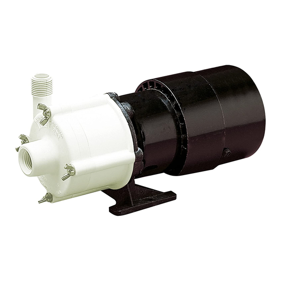
PUMP CONSTRUCTION
The patented magnetic drive pump design consists of a cylindrical
drive magnet attached to the motor shaft, which rotates around a
chemical-resistant plastic separator housing. Inside this housing is a
VOLTS
1/2"
1/2"
4-MD*
115
FNPT
MNPT
1/2"
1/2"
5-MD
115
FNPT
MNPT
*Not recommended for 50Hz operation. Possible motor overheating will occur in some applications.
**Open = Open motor, FC = fan cooled, PSC = permanent split capacitor
NOTE: Data shown is catalog performance. 230V data is the same as 115V for each frequency.
MODEL
4-MD
5-MD
CAREFULLY
BEFORE
OPERATE,
OR
SERVICE
HAZARDS.
PROTECT
TO
COMPLY
WITH
THESE
MOTOR
HERTZ
PHASE H.P. WATTS AMPS
213
2.4
60
1
1/12
214
3.1
50
200
2.1
60
1
1/8
155
1.9
50
magnet fixed to the impeller. The impeller assembly is free to rotate
on a spindle that is supported at both ends. The spindle is held
captive and does not turn. Front and rear thrust washers are utilized
as wear bearings. The washers are held captive and do not revolve.
This prevents wear on the shaft. With the magnetic coupling the
motor drives the impeller. This coupling eliminates the conventional
shaft seal and its possibility of leakage.
The pump's plastic parts are made of glass-filled polypropylene.
The spindle shaft and thrust washers are titanium. The impeller-
driven magnet is uncoated Ceramagnet A (barium ferrite) type
ceramic, and the static O-ring seal is Buna-N.
This pump is assembled and tested at the factory, and is ready
for immediate use. It may be installed in any position, including
vertically with the pump head down. To ensure proper plumbing
connections, see the SPECIFICATIONS table to determine the
intake and discharge sizes of your pump. Use thread sealer on
all pipe connections and hand-tighten only. Tighten all wing nuts
before operating the pump. The motor nameplate lists all electrical
data. Make sure the pump is connected to proper voltage before
operating. When wiring a pump with no plug, the green (or green/
yellow) wire is ground, and the other two are line (live).
Do not allow the pump to run dry (without liquid). This pump is
not submersible; operate it only in the in-line mode. Do not put
the pump into liquid. Install the pump in a dry area, protected from
splashing. This pump is not self priming; it must be installed so that
the pump head (volute) is flooded when the pump is started. That
is, the inlet of the pump must be below the level of the surface of the
liquid being pumped (Figure 1).
Do not restrict the intake side of the pump. Connections on the intake
side should not be of smaller inside diameter pipe or tubing or hose
than the intake inside diameter of the intake thread designation. If
reduced flow is required, install a valve or other restriction device on
the discharge side. When using a valve, the pump can be throttled
to provide various flow rates and pressures without harming the
motor or the pump parts.
FIGURE 1
SPECIFICATIONS
GALLONS PER MINUTE @ HEAD
SHUTOFF
MOTOR
MAX.
HEAD
TYPE**
PSI
(FT.)
1'
3'
10.2
23.7
11.5
11.0
OPEN-
FC
7.1
16.4
13.3
12.7
15.0
34.6
15.1
14.6
OPEN-
FC
PSC
9.7
22.4
13.8
13.3
PUMP MATERIALS
INSTALLATION
DIMENSIONS
6'
9'
15'
18'
24'
H
10.0
9.1
6.5
4.7
--
4.3"
4.0"
11.8
10.0
4.3
--
--
13.3
12.5
10.6
9.6
7.3
5.6"
5.4"
12.3
11.2
8.8
7.3
--
WEIGHT
PACKED
W
L
(LBS.)
8.9"
8.5
8.3"
9.3
Advertisement

Related Manuals for Little Giant 4-MD


Summary of Contents for Little Giant 4-MD
- Page 1 Front and rear thrust washers are utilized MODEL as wear bearings. The washers are held captive and do not revolve. Franklin Electric Co., Inc. 4-MD This prevents wear on the shaft. With the magnetic coupling the P. O. Box 12010 Oklahoma City, OK 73157-2010 motor drives the impeller.
- Page 2 Any product that should fail for either of the above two reasons and is still within room temperature. the warranty period will be repaired or replaced at the option of Little Giant 6. Product abuse by customer. Pump Company, Inc. dba Franklin Electric Water Transfer Systems (hereafter Any oral statements about the product made by the seller, the manufacturer, “the Manufacturer”) as the sole remedy of buyer.