
Subscribe to Our Youtube Channel
Summary of Contents for Goepel basicCAN 61 PLUS
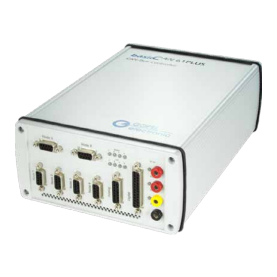
- Page 1 61 PLUS USB Controller User Manual (Translation of Original docu) Document Version 1.5 GOEPEL electronic GmbH Goeschwitzer Str. 58/60 •D-07745 Jena + 49-3641-6896-597 • ats_support@goepel.com • www.goepel.com...
- Page 2 The hardware and software might be modified also without prior notice due to technical progress. In case of inaccuracies or errors appearing in this manual, GOEPEL electronic GmbH assumes no liability or responsibility. Without the prior written permission of GOEPEL electronic GmbH, no part of this documentation may be transmitted, reproduced or stored in a retrieval system in any form or by any means as well as translated into other languages (except as permitted by the license).
-
Page 3: Table Of Contents
..............3-3 RONT ..............3-4 ............... 3-4 UNCTION 3.5.1 Status LEDs ............3-4 3.5.2 Supply of basicCAN 61 PLUS ........3-5 3.5.3 Test object Supply ..........3-5 3.5.4 OnBoard Interfaces ..........3-6 3.5.5 FlexRay Extension board ......... 3-7 3.5.6 CAN Extension board ..........3-8 3.5.7... -
Page 5: Notes On The Ec Declaration Of Conformity
Goeschwitzer Straße 58-60 D-07745 Jena With the EC Declaration of Conformity we declare the compliance of the GOEPEL electronic GmbH product described in this Manual with the requirements of the Directive 2006/95/EG – Low Voltage Directive and with the Directive 2004/108/EG about the Electromagnetic Compatibility. -
Page 7: Installation
As a rule hardware installation for basicCAN 61 PLUS means to connect the power supply cable and the USB or Ethernet cable to the control PC. Please use the supplied USB cable to connect the basicCAN 61 PLUS stand-alone device to the PC’s USB interface. Other cables may be inapplicable. - Page 8 After the installation, you can check whether the unit is properly embedded by the system. As an example, the following figure shows the successful embedding of four basicCAN 61 PLUS devices (each device appears as USB 6153 in the Device Manager): Figure 2-1:...
-
Page 9: Ethernet
IP Address (see also Addressing). This IP Address can be changed by the HardwareExplorer. The newly set IP Address becomes effective after a restart. Figure 2-2: IP Address in the GOEP EL electronic Hardw areEx plorer basicCAN 61 PLUS – User Manual... -
Page 11: Hardware
Hardware Hardware Definition The basicCAN 61 PLUS stand-alone device of GOEPEL electronic GmbH, based on the corresponding USB 6153 USB/ Ethernet board, should be connected to a PC or laptop. It was developed for applications out of complex test systems. -
Page 12: Technical Data
3.2.1 Dimensions The basicCAN 61 PLUS has the following dimensions: 230 mm x 169 mm x 82 mm (L x W x H) ¨ 3.2.2 Basic A basicCAN 61 PLUS has the following basic characteristics: Characteristics Indication Min. Typ. Max. -
Page 13: Front View
Node 4 CAN 4 (optionally, also LIN or K-Line possible) ‡ Analog Analog E/ A 1..4 (or ..6, optionally) ˆ Digital Digital-E/ A 1..4 (optionally ..8) ‰ KL30 KL15 KL31 Outputs for test object supply (red) (yellow) (black) basicCAN 61 PLUS – User Manual... -
Page 14: Rear View
ƒ „ • Ethernet Ethernet connection ‚ USB USB 2.0 connection ƒ ext. Power basicCAN External supply input for basicCAN 61 PLUS „ ext. Power Front External supply input for Test object (red - plus, black - minus) Function 3.5.1 Status... -
Page 15: Supply Of Basiccan 61 Plus
Hardware 3.5.2 Supply of For operating the basicCAN 61 PLUS, there is an external power supply of 7..25 VDC required. basicCAN For this, you can use the ext. Power basicCAN connector for the 61 PLUS delivered AC adaptor plug (12 VDC) at the device’s rear side, with coaxial power plug (2.1 x 5.5 mm/ plus polarity inside). -
Page 16: Onboard Interfaces
Hardware 3.5.4 OnBoard The basicCAN 61 PLUS has two (optionally up to six) Communication interfaces, designed as CAN 2.0B interfaces using the TJA1041A Interfaces Highspeed CAN Transceiver. Optionally it is possible to plug in different/ further transceivers (totally 4, that means not for the CAN Extension board). -
Page 17: Flexray Extension Board
Hardware 3.5.5 FlexRay The basicCAN 61 PLUS board hast two extension sockets at its top side to plug in FlexRay Extension boards. Each board has an Extension board independent FlexRay controller and two FlexRay transceivers, providing full dual channel functionality. -
Page 18: Can Extension Board
(G-API command G_Lin_PullUpResistor_Enable à Master, deactivation by G_Lin_PullUpResistor_Disable à Slave). In the deactivated state, the internal termination resistance of the LIN transceiver is effective (typical 30kΩ for TJA1020). basicCAN 61 PLUS – User Manual... -
Page 19: Digital Io
Hardware 3.5.7 Digital IO All in all your basicCAN 61 PLUS has up to 8 digital inputs and outputs. The 1..4 onboard inputs and outputs respectively have the following parameters: Symbol Indication Min. Typ. Max. Unit Remarks Digital inputs 1..4 (onboard) - Page 20 Hardware Figure 3-6: Circuit diagram extract of onboard Digital Inputs 1..4 Figure 3-7: Circuit diagram extract of onboard Digital outputs 1..4 3-10 basicCAN 61 PLUS – User Manual...
-
Page 21: Io Extension
Additional analog and digital inputs and outputs as well as various interfaces become available by plugging in an extension board. Extension GOEPEL electronic GmbH offers two different types: Type 1 and Type 2. The Type 1 IO Extension board has additional resources as follows: Symbol Indication Min. - Page 22 Hardware Figure 3-8: Circuit diagram extract of Digital inputs 5..8 for IO Ex tension board Type 1 Figure 3-9: Circuit diagram extract of Digital outputs 5..8 for IO Ex tension board Type 1 3-12 basicCAN 61 PLUS – User Manual...
- Page 23 Figure 3-10: Circuit diagram ex tract of Analog inputs 1..6 for IO Ex tension board Type 1 Figure 3-11: Circuit diagram ex tract of Analog outputs 1..6 for IO Ex tension board Type 1 basicCAN 61 PLUS – User Manual 3-13...
- Page 24 Number of inputs Input voltage Resolution Input resistance kΩ Analog outputs Number of outputs Output voltage Supply via pin UEXT Output current per channel Resolution External IO Voltage input U EXT_IO UEXT External IO Voltage 3-14 basicCAN 61 PLUS – User Manual...
- Page 25 Figure 3-12: Circuit diagram ex tract of Digital inputs 5..8 for IO Ex tension board Type 2 Figure 3-13: Circuit diagram ex tract of Digital outputs 5..8 for IO Ex tension board Type 2 basicCAN 61 PLUS – User Manual 3-15...
- Page 26 Figure 3-14: Circuit diagram ex tract of Analog inputs 1..4 for IO Ex tension board Type 2 Figure 3-15: Circuit diagram ex tract of Analog outputs 1..4 for IO Ex tension board Type 2 3-16 basicCAN 61 PLUS – User Manual...
-
Page 27: Addressing
Hardware 3.5.9 Addressing basicCAN 61 PLUS units provide a 1Gbit Ethernet interface and a USB 2.0 interface. Both interfaces can be used for the communication of the unit with the host PC. In case of using the Ethernet interface, the device can be controlled via the default IP Address 192.168.1.62, Port 5134, which can be changed if... -
Page 28: Connector Pinout
Node 1..4 connectors are not interconnected internally. If required, an external voltage can be supplied for each of these connectors (before, the internal voltage must be switched off, see OnBoard Interfaces). 3-18 basicCAN 61 PLUS – User Manual... - Page 29 The following table shows the pinout of the Analog frontal connector for IO Extension Type2 (optionally assigned, type D-SUB 15poles female): Pin Signal Pin Signal ANALOG_IN1 ANALOG_IN2 ANALOG_IN3 ANALOG_IN4 Not used Not used ANALOG_OUT1 ANALOG_OUT2 ANALOG_OUT3 ANALOG_OUT4 Not used Not used UEXT basicCAN 61 PLUS – User Manual 3-19...
- Page 30 The pinout of the Digital connector when the IO Extension is not mounted is indicated by bold characters. The GND potentials of the Node 1..4, Node A/ B, Analog and Digital connectors are internally interconnected. 3-20 basicCAN 61 PLUS – User Manual...
-
Page 31: Product Information
1 per device; this option is useable independent from and additional to options CAN/ LIN/ K-Line and FlexRay nodes General Input/ Output Module for basicCAN 61 PLUS devices incl. 4 analog Inputs and 4 analog Outputs, 4 digital Inputs and 4 digital Outputs... - Page 32 Runtime module for executing the rest bus simulation files ( files) created by Net2Run. Net2Run Runtime This option is necessary for each basicCAN 61 PLUS device. Software programming environment (Windows host) to build G-API based on-board UserCode programs for basicCAN 61 PLUS; Net2Run IDE...
-
Page 33: Software
Software Software There are the following ways to integrate basicCAN 61 PLUS hardware in your own applications: G-API Programming ¨ UserCode Programming ¨ basicCAN 61 PLUS – User Manual... -
Page 34: G-Api Programming
Software G-API Programming The G-API (GOEPEL-API) is the C-based user interface for GOEPEL electronic hardware under Windows ® It provides a wide, hardware independent command set for CAN, LIN, K-Line, FlexRay, MOST, LVDS, ADIO and Diagnostic services. No matter whether a PXI/ PCI, USB or Ethernet device is used, the commands remain the same. -
Page 35: Usercode Programming
Software UserCode Programming basicCAN 61 PLUS devices can execute user programs direct on their PowerPC processor. This requires the UserCode run-time module being enabled. The UserCode run-time module is an option for basicCAN 61 PLUS devices (plus other GOEPEL devices) and requires one license per unit. - Page 36 Figure 4-1: N et2R un IDE W indow Please consult the G-API documentation for further information. This documentation and the installation software are located in the G-API folder of the supplied “Product Information” CD. basicCAN 61 PLUS – User Manual...
- Page 37 Test object ....3-5 Ethernet ....2-5, 3-17 Extension Test object FlexRay ......3-7 Supply ......3-5 IO ....... 3-11 Transceivers ...... 3-6 FlexRay extension ....3-7 UserCode ....3-22, 4-3 G-API ....... 4-2 basicCAN 61 PLUS – User Manual...
Need help?
Do you have a question about the basicCAN 61 PLUS and is the answer not in the manual?
Questions and answers