
Summary of Contents for Rosemount Analytical 54C
- Page 1 Instruction Manual 5100054C Model 54C July 1999 Conductivity Microprocessor Analyzer...
- Page 2 ELECTRICAL SHOCK HAZARD READ THIS PAGE BEFORE PROCEEDING! Making cable connections to and servicing this Rosemount Analytical designs, manufactures, and tests instrument require access to shock hazard level its products to meet many national and international stan- voltages which can cause death or serious dards.
-
Page 4: Table Of Contents
MODEL 54 C TABLE OF CONTENTS MODEL 54 C MICROPROCESSOR ANALYZER TABLE OF CONTENTS Section Title Page 1 1 . . 0 0 I I N N S S T T A A L L L L A A T T I I O O N N ..........................................1 1 - - 1 1 Preparation for Installation.................. - Page 5 MODEL 54 C TABLE OF CONTENTS TABLE OF CONTENTS (Continued) LIST OF FIGURES Figure No. Title Page Panel Mounting..................Panel Mounting Dimensions..............Two-inch Pipe and Wall Mounting Dimensions ........Wall Mounting ..................Pipe Mounting ..................Conduit Openings ................Output, Power Input and Sensor Wiring (Code 08)......Wiring of Contacting Conductivity Sensors..........
-
Page 6: Preparation For Installation
1-2. Insert the instrument enclosure Confirm that all items shown on the packing list through the front of the panel cutout and align are present. Notify Rosemount Analytical if items the panel mounting brackets as shown. are missing. Insert two mounting bracket screws through... -
Page 7: Panel Mounting Dimensions
MODEL 54 C SECTION 1 INSTALLATION WHEN INCH AND METRIC DIMS ARE GIVEN MILLIMETER INCH DWG. NO. REV. 40005401 FIGURE 1-2. Panel Mounting Dimensions... -
Page 8: Two-Inch Pipe And Wall Mounting Dimensions
MODEL 54 C SECTION 1 INSTALLATION 1.2.2 Wall or Surface Mounting (P/N 2002577) 1.2.3 Pipe Mounting (P/N 2002577) Mount the bracket to the analyzer as shown in Attach the mounting bracket to the rear of the Figure 1-3. analyzer and tighten the four screws as shown in Figure 1-3 Figure 1-5. -
Page 9: Wiring The Analyzer
MODEL 54 C SECTION 1 INSTALLATION FIGURE 1-4. Wall Mounting FIGURE 1-5. Pipe Mounting 1.3 WIRING THE ANALYZER There are five conduit openings in the bottom of the ana- terminal strips. Mount NEMA 4X or IP65 conduit plugs lyzer housing which accommodate 1/2 inch conduit fit- (supplied) into unused holes in the base of the analyz- tings or PG 13.5 cable glands. -
Page 10: Conduit Openings
CAUTION 1.3.2 Input Power Selection (Code -08). The Model DO NOT apply power to the instrument 54C -08 is field selectable for 115Vac or 230Vac until all electrical connections are verified 50/60Hz. Refer to Drawing Number 400054C06. and secure. AC connections and groun- ding must be in compliance with UL 508 and/or local electrical code. -
Page 11: Output, Power Input And Sensor Wiring (Code 08)
MODEL 54 C SECTION 1 INSTALLATION DWG. NO. REV. 40054C06 FIGURE 1-7. Output, Power Input and Sensor Wiring (Code -08) -
Page 12: Wiring Of Contacting Conductivity Sensors
MODEL 54 C SECTION 1 INSTALLATION ENDURANCE MODEL 400 SERIES WIRING DWG. NO. REV. 40054C02 FIGURE 1-8. Wiring of Contacting Conductivity Sensors... -
Page 13: Wiring Of Inductive Conductivity Sensors
MODEL 54 C SECTION 1 INSTALLATION AND QUICK START-UP DWG. NO. REV. 40054C03 FIGURE 1-9. Wiring of Inductive Conductivity Sensors... -
Page 14: Operating Display
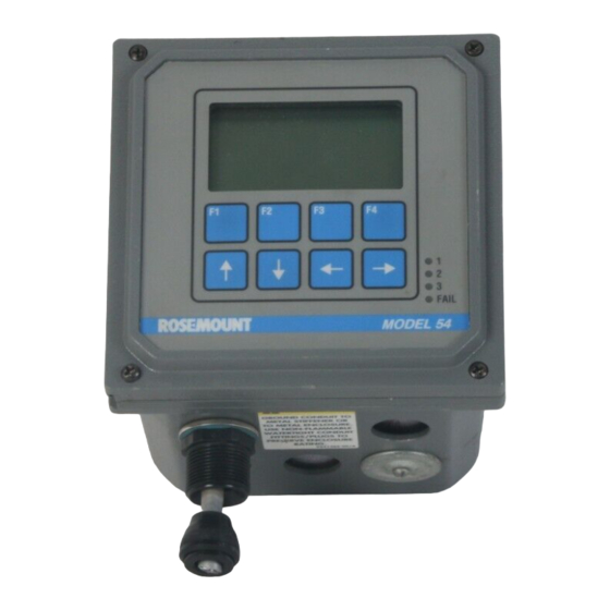
MODEL 54 C SECTION 2 DESCRIPTION OF CONTROLS AND INDICATORS SECTION 2.0 DESCRIPTION OF CONTROLS AND INDICATORS 2.1 OPERATING DISPLAY 2.3 ARROW KEYS Figure 2-1 shows the Model 54 C Analyzer front panel The up and down arrow keys move the reverse video with the operating display screen shown. - Page 15 MODEL 54 C SECTION 3.0 PROGRAMING THE ANALYZER SECTION 3.0 PROGRAMING THE ANALYZER The analyzer arrives from the factory configured and ready to operate for use with inductive (toroidal) con- ductivity sensors. If Series 100 contacting conductivity sensor is used the analyzer must be configured as “contacting”...
- Page 16 MODEL 54 C SECTION 3 PROGRAMING THE ANALYZER Table 3-1. Conductivity Settings List (Continued) ITEM RANGES FACTORY SETTINGS USER SETTINGS B. Outputs (Section 3.4) Continued 3. Output 2 (a) Measurement Selection Temperature/Conductivity Temperature _______ (b) Current Range 4-20 mA/0-20 mA 4-20 mA _______ (c) Dampening...
-
Page 17: Outline Of Menu Levels
MODEL 54 C SECTION 3 PROGRAMING THE ANALYZER Accessing Calibrate, Program and Configure Level 2 Program. To access the program level from Menus Operating configuration changes are made at the main menu, place the cursor over “Program” using the levels shown in Figure 3-1. -
Page 18: Changing Alarm Setpoints
MODEL 54 C SECTION 3 PROGRAMING THE ANALYZER 3.1 CHANGING ALARM SETPOINTS This section describes how the three alarm setpoints can be changed. Alarm setpoints Rerange outputs From the operating display, press any key to obtain the main menu. Configure With the down arrow key, move the cursor to “Program”... -
Page 19: Reranging And Testing Outputs
MODEL 54 C SECTION 3 PROGRAMING THE ANALYZER 3.2 RERANGING AND TESTING OUTPUTS This section describes how the outputs (4-20 or 0-20 mA) can be Alarm setpoints reranged. Rerange outputs From the main menu, move the cursor down to “Program” and press Configure Enter (F4). -
Page 20: Configuration Of Display Options
MODEL 54 C SECTION 3.0 PROGRAMING THE ANALYZER 3.3 CONFIGURATION OF DISPLAY OPTIONS This section describes the procedure for changing what is shown on the Display operating display. Outputs From the program menu, move the cursor to “Configure” and press Enter (F4). -
Page 21: Configuration Of Output Parameters
MODEL 54 C SECTION 3 PROGRAMING THE ANALYZER 3.4 CONFIGURATION OF OUTPUT PARAMETERS This section describes the options available for configuration of the Display outputs. The designation “O1” refers to output 1. The designation “O2” refers to output 2. Outputs From the program menu . - Page 22 MODEL 54 C SECTION 3 PROGRAMING THE ANALYZER Menu Item Options Temperature O2 Output 2 Measurement Temp/Conductivity O2 Current range* 4-20 mA/0-20mA 4-20 mA O2 Output 2 Dampen 0-255 sec. O2 Dampen: 0 sec *If this value is changed, be sure to rerange output as described in Exit More Enter...
-
Page 23: Configuration Of Alarm Parameters
MODEL 54 C SECTION 3 PROGRAMING THE ANALYZER 3.5 CONFIGURATION OF ALARM PARAMETERS This section explains configuration of the alarms. The designations “A1”, “A2”, “A3” and “A4” refer to relays 1,2,3 and 4, respectively. From the program menu select configure menu and Enter (F4). With Display the cursor on “Alarms”, press Enter (F4). - Page 24 MODEL 54 C SECTION 3 PROGRAMING THE ANALYZER Menu Item Options High A3 alarm 3: Configuration Low alarm/High alarm/ Off (not used) A3 Hys: 000 % A3 alarm 3: Hysteresis (deadband)* 0-25 % A3 Delay: 0 Sec A3 alarm 3: Delay time before relay activation and deactivation (can prevent chatter) 0-99 sec Exit...
-
Page 25: Configuration Of Security Levels
MODEL 54 C SECTION 3 PROGRAMING THE ANALYZER 3.6 CONFIGURATION OF SECURITY LEVELS This section describes programming of three levels of security: Lock out all access (read main screen only) Lock out program features (only calibration is allowed) III. Lock out configuration features (only calibration, alarm setpoint and rerange output setpoints (4 and 20 mA values) are allowed) For convenience, the level 3 security code will be accepted at levels 1 and 2 and the level 2 security code will be accepted at level 1. -
Page 26: Configuration Of Temperature Sensor (Rtd)
MODEL 54 C SECTION 3 PROGRAMING THE ANALYZER 3.7 CONFIGURATION OF TEMPERATURE SENSOR (RTD) TYPE This section explains how to change the temperature sensor type. From the program menu, display configure menu, and press Enter Security (F4) and More (F3). Move the cursor to “Temperature sensor” and press Enter (F4). - Page 27 SECTION 4.0 CALIBRATION 4.1 INITIAL SETUP We recommend complete configuration (Section 3.0) of the Model 54C Standardize cond. before calibration. Calibration consists of entering the cell constant, zeroing the sensor in air, and entering the temperature slope of the Initial setup process.
- Page 28 MODEL 54 C SECTION 4 CALIBRATION Manual temperature slope: If the temperature slope of the process Manual slope input is known, use the cursor keys to display the temperature slope value and press Enter(F4). If you do not know the exact temperature slope Temp slope calibration value, but wish to approximate it, refer to the following guide.
- Page 29 MODEL 54 C SECTION 4 CALIBRATION When the temperature and sensor have stabilized at the first tem- Slope: 2.00%/°C perature enter the conductivity reading from B above and press Enter (F4). Temperature slope G. Adjust the sample’s temperature to the other normal temperature calibration complete extreme of the process.
-
Page 30: Initial Setup
MODEL 54 C SECTION 4 CALIBRATION 4.2 TEMPERATURE ADJUSTMENT For accurate temperature correction, the temperature reading may need adjustment. The following steps should be performed with the sensor on line or in a grab sample near the operating temperature. Observe the analyzer temperature reading. Make sure the sensor has accli- Initial setup mated to the process temperature. -
Page 31: Conductivity Standardization
MODEL 54 C SECTION 4 CALIBRATION 4.3 CONDUCTIVITY STANDARDIZATION For maximum accuracy, standardize the sensor in the process or a Standardize Cond process grab sample. Initial setup From the operating display, press any key to obtain the main menu. With Adjust temperature the cursor on “Calibrate”, press Enter (F4). - Page 32 MODEL 54 C SECTION 5 DIAGNOSTICS AND TROUBLESHOOTING SECTION 5.0 DIAGNOSTICS AND TROUBLESHOOTING The MODEL 54 Conductivity Analyzer automatically Troubleshooting is easy as 1, 2, 3 . . . searches for fault conditions that would cause an error Step 1 Look for a diagnostic fault message, on the in the measured reading.
-
Page 33: Diagnostic Messages
MODEL 54 C SECTION 5 DIAGNOSTICS AND TROUBLESHOOTING 5.1 DIAGNOSTIC MESSAGES. The Model 54 C software diagnostics constantly moni- Note the message and refer to Table 5-1 for an expla- tor the loop for possible problems. If you encounter an nation of the message and a list of the possible prob- operational problem check the display for a fault or error lems that triggered it. - Page 34 MODEL 54 C SECTION 5 DIAGNOSTICS AND TROUBLESHOOTING KEYSTROKE GUIDE FOR CHANGING LANGUAGES From the operating display*, press any key to obtain the main menu. Calibrate Display text will be in English, French, Spanish, German or Italian. With the down arrow key, move the cursor to “Program/Programme/- Diagnostic Variables Programm/Programmazione”...
-
Page 35: Displaying Diagnostic Variables
To redisplay the first screen, press More (F3). To return to the main screen, press Exit (F4) until the main Version: 54C.X screen is reached. NOTE “X” in example will be a numerical value. Software versions will also... -
Page 36: Quick Troubleshooting Guide
5.3.1 FIELD TROUBLESHOOTING. When it is appar- C. If the previous two steps did not indicate the ent by grab sample analysis that the model 54C ana- source of the problem, the next step is to isolate lyzer is giving inaccurate readings, the following pro- the problem to either the sensor or the Model 54C cedure should be followed. -
Page 37: Systematic Troubleshooting
MODEL 54 C SECTION 5 DIAGNOSTICS AND TROUBLESHOOTING 5.4 SYSTEMATIC TROUBLESHOOTING Not all problems that you encounter will be typical. If Step 1 Follow the applicable troubleshooting flow you are unable to resolve your problem using the chart: Quick Troubleshooting Guide, Table 5-2, then try the Step 2 Refer to the tests and instructions indicated by... -
Page 38: Rtd Resistance Values
MODEL 54 C SECTION 5 DIAGNOSTICS AND TROUBLESHOOTING 5.5 RTD RESISTANCE VALUES 5.6 CIRCUIT BOARD Table 5-3 (below) is a ready reference of RTD resist- REPLACEMENT ance values at various temperatures. These are used for test and evaluation of the sensor. If it is necessary to replace the CPU Circuit Board or Power Supply Circuit Board, specific procedures for NOTE... - Page 39 MODEL 54 C SECTION 6 REPLACEMENT PARTS AND ACCESSORIES SECTION 6.0 REPLACEMENT PARTS AND ACCESSORIES INDEX PART NUMBER DESCRIPTION 23548-00 CPU Circuit Board 23710-00 Power Supply Circuit Board (115/230Vac) -Code -08 23537-00 LCD Display Circuit Board 23540-00 Front Panel Assembly 33281-00 Hinge Pin 33286-00...
- Page 40 The actual value of the drive voltage generated by the to the reference temperature (usually 25°C). by accu- Model 54C (either 1 volt peak-to-peak or 0.1 volt peak- rately measuring the process temperature by means of to-peak) is determined by the conductivity being a RTD located in the conductivity sensor.
- Page 41 MODEL 54 C SECTION 7 THEORY OF OPERATION INTERVAL TIMER. The interval timer may be used for OUTPUT LOGIC. The behavior of the Model 54 ana- periodic sensor cleaning, or process adjustment. lyzer's outputs and relays are determined by various states called 'modes'.
-
Page 42: Features And Applications
The two independent, isolated outputs provide 4-20 The Model 54C utilizes either a PT-100 or a PT-1000 or 0-20 mA signals for conductivity and temperature. RTD located in the sensor to display temperature and... -
Page 43: Physical Specifications
The temperature slope is factory set at 2% as a representative value, but each conductive solu- tion has its own set of temperature vs. concentration curves. The Model 54C will automatically calculate the temperature slope for any given solution, or permit manual adjustment of the temperature slope if already known. -
Page 44: Ordering Information
MODEL 54 C SECTION 8 DESCRIPTION AND ORDERING INFORMATION CONTACTING SENSORS Conductivity Sensor 140, 141 401-14 Model Number 402/403 402/403 400/402/403 400/402/403 Cell Constant 0.01 10.0 Minimum Range 2000 Maximum Range 2,000 4,000 10,000 20,000 200,000 FULL SCALE MICROSIEMENS/cm INDUCTIVE SENSORS Conductivity Sensor Model Number 222 (1in.) - Page 45 Before returning a product for repair, call 1-949-863-1181 for a Return Materials Call Rosemount Analytical for authorization. Authorization (RMA) number. Supply the purchase order number, and make 9.2 WARRANTY REPAIR.
- Page 46 MODEL 54 C APPENDIX APPENDIX...
- Page 47 MODEL 54 C APPENDIX...
- Page 48 Our staff of trained professionals are ready to provide the information you need. If you are placing an order, verifying delivery, requesting application information, or just want to contact a Rosemount Analytical representative, a toll-free call to 1-800-854-8257 will provide you with the right people, the right answers, right now.
- Page 49 SAMPLE OR MATERIAL THAT HAVE BEEN EXPOSED TO OR USED IN AN ENVIRONMENT OR PROCESS THAT CONTAINS A HAZARDOUS MATERIAL ANY OF THE ABOVE THAT IS SUBMITTED TO ROSEMOUNT ANALYTICAL WITHOUT THE MSDS WILL BE RETURNED TO SENDER C.O.D. FOR THE SAFETY AND HEALTH OF OUR EMPLOYEES. WE THANK YOU IN ADVANCE FOR COMPLIANCE TO THIS SUBJECT.
- Page 50 FOLD ALONG DOTTED LINES...
- Page 51 For Customer Support Mike Stoessl 24 hours a day/365 days a year, President, Rosemount Analytical-Uniloc Division Call 1-800-854-8257 Complete this registration, fold it in thirds so the return address shows, and drop it in any mailbox, or visit our web- site at www.RAuniloc.com and register on-line to double your standard warranty from 1 year to 2 years.
- Page 52 AND IMPLIED WARRANTIES OF MERCHANTABILITY AND FITNESS FOR A PARTICULAR PURPOSE. RETURN OF MATERIAL Material returned for repair, whether in or out of warranty, should be shipped prepaid to: Rosemount Analytical Inc. Uniloc Division 2400 Barranca Parkway Irvine, CA 92606...
- Page 53 CUSTOMER SUPPORT CENTER 1-800-854-8257 ON-LINE ORDERING NOW AVAILABLE ON OUR WEB SITE http://www.RAuniloc.com Credit Cards for U.S. Purchases Only. Rosemount Analytical Inc. Uniloc Division 2400 Barranca Parkway Irvine, CA 92606 USA Tel: (949) 863-1181 http://www.RAuniloc.com © Rosemount Analytical Inc. 1998...
Need help?
Do you have a question about the 54C and is the answer not in the manual?
Questions and answers