Advertisement
Publish Date: Feb. 2020
EVPP164SI2021 Rev. 1
USA/North America
©Everlast Power Equipment
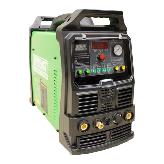
AC/DC
PULSE
160A
DC
130A
DC
40A
120/240V
1 Phase
Welders, Plasma Cutters, Multi-Process
Safety, Setup and General Use Guide
Operator's Manual
FUNCTION: AC/DC TIG with Pulse Function/ DC Stick/ Plasma
PURCHASE DATE:
WELDER SERIAL NUMBER:
OPTIONAL ACCESSORY SERIAL NUMBER:
Advertisement
Table of Contents

Related Manuals for Everlast PowerPro 164Si


Summary of Contents for Everlast PowerPro 164Si
- Page 1 Publish Date: Feb. 2020 EVPP164SI2021 Rev. 1 USA/North America ©Everlast Power Equipment AC/DC PULSE 160A Safety, Setup and General Use Guide 130A FUNCTION: AC/DC TIG with Pulse Function/ DC Stick/ Plasma PURCHASE DATE: WELDER SERIAL NUMBER: OPTIONAL ACCESSORY SERIAL NUMBER: Operator’s Manual...
- Page 2 TABLE OF CONTENTS SPECIAL NOTICE AND CALIFORNIA PROPOSITION 65 WARNING CUSTOMER GREETING AND EXPLANATION OF PROCEDURES WARRANTY AND CONTACT INFORMATION SAFETY DISCLAIMER AND HF WARNING SAFETY WARNINGS, DANGERS, CAUTIONS AND INSTRUCTIONS GENERATOR OPERATION INFORMATION SPECIFICATIONS, INCLUDING DUTY CYCLE AND INPUT AMPERAGE INFORMATION GETTING STARTED, UNPACKING YOUR UNIT AND INSPECTION CONNECTING YOUR UNIT TO THE POWER SOURCE AND WIRING INFORMATION SHIELDING GAS INFORMATION AND CONNECTION OF GAS AND AIR COMPRESSOR REGULATORS...
-
Page 3: California Proposition 65 Warning
Due to multiple variables that exist in the welding field and the changing nature of it and of the Everlast product line, Everlast Power Equipment INC. does not guarantee the accuracy, completeness,... - Page 4 Many issues can be resolved over the phone. If the issue cannot be resolved over the phone/email, you may be given an op- tion to return the unit, or have a part shipped to you, at Everlast’s discretion. Keep in mind, you may be asked questions that seem basic, or ele- mentary to your knowledge base.
-
Page 5: Who Do I Contact
Warranties and service policies and procedures vary from country to country and are maintained and supported by the region- al or in country distributor of Everlast welding equipment. USA Customers Only: For full details on the 5 year parts and labor warranty, 30 day satisfaction policy, terms of sale, and how to proceed with a war- ranty claim, please visit: https://www.everlastgenerators.com/standard-warranty. - Page 6 Safe operation and proper maintenance is your responsibility. Everlast is dedicated to keeping safety a top priority. While we have compiled this operator’s manual to instruct you in basic safe operation and maintenance of your Everlast product, it is no substitute for observing safe welding practices and behavior. Safe welding and related cutting operations require basic knowledge, experience and ultimately the exercise of common sense.
- Page 7 It is your responsibility to make certain that the use of this welder is restricted to per- sons who have read, understand and follow the warnings and instructions in this manual. If you or the operator needs further instruction, contact Everlast welding support at 1-877 755 -9353 ext. 204 or seek qualified professional advice and training.
- Page 8 Safety Warnings, Dangers, Cautions and Instructions DANGER! Welding and cutting operations pose serious inhalation hazards. Some of these hazards are immediate while others are cumulative in their effect. Do not weld in enclosed spaces or in areas without adequate ventilation. Fumes and gases released in the welding and cutting operations can be toxic.
- Page 9 Safety Warnings, Dangers, Cautions and Instructions CAUTION! Trip Hazards exist around welders. Cords, cables, welding leads and hoses pose a trip hazard. Be aware of their location and inform others of their location. Tape and se- cure them so they will stay out of high traffic areas. CAUTION! Welded metal can stay hot long after welding is completed.
- Page 10 WARNING! Never use the electrical power outlet on the back of this machine for anything other than powering an Everlast brand water cooler. This is a special outlet designed to produce 240V with limited amperage draw. No other device or brand should be used in conjunction with this unit’s outlet.
-
Page 11: Specifications
National Electric Code (NEC) and local codes. If needed, refer the electrician to Article 630 of the NEC during consultation to determine proper application and wiring needs. Use the I1MAX and the I1EFF ratings listed above to determine the proper breaker and conductor (wire) sizing required. Everlast welders are designed around use in industrial wiring applications and are intended to be used with modern electrical systems. -
Page 12: Getting Started
If any item is damaged or missing, please inform the immediate area you are welding. The fan(s) found in your unit Everlast within 72 hours of product receipt. See pages 4 and 5 for are powerful enough to create strong air turbulence in the weld area. - Page 13 If you are not qualified to make slow blow fuse, or delayed trip breaker protecting the circuit. The in- these connections, don’t. Everlast is in no way liable for any damag- rush current of this unit can exceed the limits of a typical 15A 120V es caused by improper connection of your welder.
- Page 14 Setup Guide Getting Started Connecting Argon shielding gas for versus connecting compressed air. This unit is equipped with only one inlet in the rear for gas supply. This means that both shielding gas for TIG welding and the Air sup- ply for plasma cutting uses the same fitting.
- Page 15 Setup Guide Getting Started CONNECT YOUR UNIT TO TIG SHIELDING GAS. rounding of the fitting shoulders. Do not use pliers, or a serrated jaw What Shielding Gas Should Be Used? wrench such as a pipe wrench or basin wrench to tighten the fitting. The design of the fitting means that no thread sealing tape or com- Selecting shielding gas for MIG is straightforward.
- Page 16 Setup Guide Getting Started CONNECT THE AIR COMPRESSOR Connect Regulator To Cylinder And Unit. What do I need to be able to plasma cut? The unit comes with everything you need as far as a basic starter kit for consumables, torch and regulator. However, you will need to supply a few things on your own.
- Page 17 Setup Guide Getting Started SELECT THE PROPER TUNGSTEN TYPE. Purchasing Tungsten can be difficult. Local suppliers tend to put a premium price on Tungsten, and may be three times an online price What Type of Tungsten Do I Use? direct from a distributor. In many areas, the choice of tungsten may Selecting the correct tungsten for your welder is important.
- Page 18 Setup Guide Getting Started Choosing the proper grind angle is important to achieving the weld As you use the tungsten (depending upon the type you have select- penetration, bead appearance, and arc cone width that you desire. ed) you will notice that the tungsten will gently form more of a point- While there is no true “one size fits all”...
- Page 19 What Size of Tungsten Do I Use? NOTICE. Everlast advertises low arc start capability on their units. Surge Am- A tungsten such as a 1/8” diameter or larger may not start as cleanly perage to establish the arc are quite low. When starting an arc, at the minimum capable start amp of this unit.
- Page 20 Setup Guide Getting Started in color coding, so match the color codes of the torch to the cooler SELECT THE PROPER TIG POLARITY AND CONNECTIONS. couplings for best results). The line exiting from the DINSE connect- Selecting polarity for TIG is quite simple. The torch will always be or is no longer a gas line but a water line.
- Page 21 PowerCool cooler. If you have any questions about purchasing the E7018, and E7014,308, 309L, 316 and hard surfacing rods are correct cooler and assembly for your welder, contact Everlast. excellent choices for use with this machine. SELECT THE PROPER STICK POLARITY.
- Page 22 Setup Guide Getting Started location for proper polarity. The design of the unit means that the plasma torch does not have its own dedicated connector or terminal. This terminal must be shared with the TIG torch. The plasma con- nector is a 30/50 DINSE Type, but is a special connector designed for use with the Plasma torch only.
- Page 23 Setup Guide Getting Started If you are needing basic help getting started TIG welding, here are some general settings and selections to get you started. This guide is intended to be only a starting point, not a completely exhaustive source. Keep in mind that no guide is a substitute for practice and experience. You may find that your final settings may be different from the ones listed.
-
Page 24: Front Panel View
Component Identification and Explanation Front Panel View Number Component Identification Component Note Protective Cover Keep cover down and in place during welding activities and in storage. Positive Terminal (+) Connect the work clamp to this terminal for all TIG welding (DC and AC) and Plasma cutting applications. (DINSE 35/50 Type, 1/2”... -
Page 25: Rear Panel View
Component Note Water Cooler Plug (240V 1ph, 4A max) This plug is to be used with Everlast water coolers only. Do not use with any other application. Input Cable and Plug* North America only: The unit may be operated on either 208-240V 1 phase (or on 120V 1 phase with the included pigtail adapter). -
Page 26: Control Panel Layout
“clean power”, and/or some internal event that caused an excessive current draw. Check for issues then attempt one reset, if this does not clear or reoccurs shortly after, contact Everlast Tech Support. Down Slope/Post Flow 0-10 Seconds Down Slope is used with 2T/4T only. - Page 27 0% electrode negative. Some brands express this with a recip- rocal value of Electrode Negative. So what would be a “safe” 30% electrode positive setting on the Everlast, becomes a 70% electrode negative setting on other brands. Everlast, along with other brands...
- Page 28 Everlast Tech Support. CAUTION! Don’t continue try to make the arc start without somewhere for the HF to travel, ie to the work piece.
- Page 29 If you need this type of start on a welder, contact Everlast for other so that arc starts are more efficient. It also allows time for the gas product information.
- Page 30 SECONDS that they are adjustable. The PowerPro 164Si has only the ability to select from two preset pulse operations. but these items have been EXAMPLE 2...
- Page 31 Component Identification and Explanation Explanation of Functions and Welding Terms been preset at a 50% value to offer an even balanced feel. arc.. Then the torch is released to terminate the arc and begin post flow. AC Pulse TIG operation is setup the same. Do not confuse AC cy- cling between EP and EN as pulse.
- Page 32 With an inverter welder, pre programmed wave forms can be generated. Although some units from Everlast offer adjusta- ble wave forms, this unit only has one wave form. This is the Ad- vanced Square wave.
- Page 33 Component Identification and Explanation 17 Series Air-Cooled Welding Torch (Typical Type) Parts and Assembly. Typical Everlast and NOVA Torch Assembly (17,18, 26 Series) (Some parts may not appear exactly the same but are equal in assembly order and type.) Tungsten not included, but available in select Consumable Kits on the website at www.everlastwelders.com.
- Page 34 Component Identification and Explanation Plasma Cutter Function Important Information and Warnings: NOTICE! The Plasma cutting function of this machine is designed to be a support function and is not designed to be the pri- mary function of this machine. The Plasma duty cycle of this machine is lower than that of a stand alone Plasma cutter (35% @ max.
- Page 35 Component Identification and Explanation Explanation of Functions and Plasma Cutting Terms instructions later in the manual to identify the type and cause of dif- What Air Pressure do I use to cut? ferent types of dross. The unit should maintain between 65 and 72 PSI while actively cutting. Edge Start Cut.
- Page 36 Component Identification and Explanation How do I edge start a plasma cut? How do I pierce start a plasma cut? Edge starts are the best type of start to promote consumable Piercing starts often result in rapid consumable wear and and torch life.
- Page 37 Everlast is not the manufacturer of the Innotec iPT series torches and TRAVEL does not offer all possible consumable types available for the torch series.
- Page 38 Component Identification and Explanation What kind of dross am I seeing? What other problems am I like to encounter? Dross identification can help you determine what is wrong with your Frequently, more than one problem may exist. Closely evaluating cuts. Use the guide below to help you improve your cut quality. all issues can help narrow down cutting problems.
- Page 39 Component Identification and Explanation How Do I Use a Lead-in? What is Kerf? When cutting an object, particularly a pattern shape, where the torch must pierce or re-fire in-line at an When you make a cut, a certain amount intersection of a cut, a lead-in cut should be employed. A lead-in is a cut that is made in the disposable of material is removed from the cut.
- Page 40 TP0080 PTF0224 Switch BX0020 PTF0450 Cable Assembly PH0295 Pilot Cable PPA0170 Nut Cup PPA0171 Small 2-Pin Plug NOTICE: Not all consumables or parts are available from Everlast. Some parts depicted are options. Some parts are replaced as a full assembly.
- Page 41 Component Identification and Explanation 7 PIN CONNECTOR FOR 10K or 22K Ω FOOT PEDAL Bridge a Jumper to Pin 7 To Pedal or Torch Switch ON/OFF Bridge a Jumper to Pin 6 To Pedal or Torch Switch ON/OFF High Middle Potentiometer (VR) Foot Pedal (10k-22k Ω) Note: This unit is designed to accept several different Ohm values, including the older 47K (50K) Ohm pedal without significantly...
-
Page 42: Troubleshooting
OVER CURRENT. Check to make sure input power cable is correct length and size. Internal unit fault or low input voltage. Possible issue running on generator with dirty power. Identify cause, plug directly into the receptacle. Cycle the switch one time. If the code does not clear, call Everlast Tech Support. - Page 43 Check gas flow. Adjust for higher flow of gas. Listen for audible click activity. Solenoid is sticking. Too short of pre- of gas solenoid. If no click is heard, then contact Everlast Support. Clean flow or post-flow weld properly. Increase pre flow or post flow.
- Page 44 Cup and/or nozzle is melting or cracking. Improper cutting technique/excessive piercing. Power input circuit breaker trips repeatedly. Improperly sized circuit. Internal issue. Contact Everlast. Arc “Blows Out” when ready to cut. Too high of air pressure. Wrong size consumable for amperage being used.
-
Page 45: Maintenance
This is important to keeping your welder running for many years into the future. It is important to note that cleaning doesn’t void your warranty, but rather ensures it! Keep your welder covered when not in use. You can purchase a cover for your welder direct from Everlast.
Need help?
Do you have a question about the PowerPro 164Si and is the answer not in the manual?
Questions and answers