
Summary of Contents for ioi CMOS
- Page 1 Flare High-Speed CMOS Area Scan Camera Series 12M180 CoaXPress User's Manual Revision 1.0 Copyright © 2015 IO Industries Inc. All rights reserved. Flare is a pending trademark of IO Industries Inc.
- Page 2 Flare 12M CXP User's Manual Notice The material contained in this manual consists of information that is proprietary to IO Industries Inc. and may only be used by the purchasers of the product and IO Industries Inc. authorized distributors or resellers. IO Industries Inc. makes no warranty for the use of its product and assumes no responsibility for any errors that may appear or for damages resulting from the use of the information contained in this manual.
- Page 3 Established in 1991, IO Industries Inc. designs high performance digital imaging products for applications in manufacturing, research, vehicle-mounted systems, and video game content creation. Products include PC-based, standalone and peripheral DVR systems; and high speed CMOS area scan digital cameras. Contact Information IO Industries Inc.
-
Page 4: Table Of Contents
Flare 12M CXP User's Manual Table of Contents 1 Introduction..........................6 1.1 Camera Highlights......................6 1.2 Sensor Specifications......................7 1.3 Cover Glass Transmittance.....................8 1.4 Spectral Response......................8 1.5 Bayer Pattern........................9 2 Mechanical..........................10 2.1 Mechanical Specifications....................11 2.2 Lens Adapters........................11 2.3 Power..........................12 2.4 External Trigger......................13 2.5 LED Status Indicator......................14 3 Camera Control........................15 3.1 Register Maps........................15 3.2 CoaXPress Output Format....................32... - Page 5 Flare 12M CXP User's Manual 3.12.2 Focus........................54 3.12.3 Reset........................54 3.13 Command Memory......................54 3.14 Camera Reset......................55 3.15 Control Packet CRC....................55 3.16 Device Discovery......................55 4 Order Numbers........................56 5 Accessories..........................57 6 Document Revision History....................58 7 Firmware Revision History....................58 IO Industries Inc. www.ioindustries.com Revision 2.0...
-
Page 6: Introduction
Flare 12M CXP User's Manual 1 Introduction The Flare 12M CoaXPress (CXP) series is a family of high-speed CMOS area scan cameras designed for a broad range of applications. Table 1 shows the camera models covered in this manual. Model... -
Page 7: Sensor Specifications
Flare 12M CXP User's Manual 1.2 Sensor Specifications Specification 12M180 Sensor CMOSIS CMV12000 Effective Pixels 4096 x 3072 Optical Area 22.5mm x 16.9mm (28.1mm diagonal) Pixel Pitch 5.5 x 5.5 µm Full Well Charge 13.5 Ke- Conversion Gain 0.075 LSB/e- Sensitivity 4.64 V/lux.s Temporal Noise... -
Page 8: Cover Glass Transmittance
Flare 12M CXP User's Manual 1.3 Cover Glass Transmittance D263 (D263T Eco) cover glass with an anti-reflective coating is used on all models. The refraction index of the glass is less than 1.5% between 400-900nm wavelength. 1.4 Spectral Response Typical spectral responses of monochrome and color 12M125 cameras, with D263 cover glass, is shown in Figure 1. -
Page 9: Bayer Pattern
Flare 12M CXP User's Manual A typical spectral response of monochrome camera (normal device) and near infrared camera (E12 device), with D263 cover glass, are shown in Figure 2. Figure 2. Monochrome and NIR spectral response 1.5 Bayer Pattern The Bayer pattern for color models is shown in Figure 3. Pixel Pixel (1,1) -
Page 10: Mechanical
Flare 12M CXP User's Manual 2 Mechanical Camera housings are made with high precision from machined aluminum. Mechanical drawings shown below. Figure 4. Mechanical drawings IO Industries Inc. www.ioindustries.com Revision 2.0... -
Page 11: Mechanical Specifications
Flare 12M CXP User's Manual 2.1 Mechanical Specifications Summary of mechanical specifications shown below. Specification Description Size 91.7 mm x 91.7 mm x 44.5 mm Weight 490 g (no lens) Mounting Holes Bottom and top: 3x 1/4”-20, 2x M4x0.7 Sides: 1x 1/4”-20, 2x M4x0.7 Front: 4x M4x0.7 Power Connector 12-pin threaded Hirose... -
Page 12: Power
Flare 12M CXP User's Manual 2.3 Power Flare 12M CXP cameras are powered using a 12-24 V ± 10% DC power source. The power connector is shown in figure 7, and the pinout is shown in Table 4. The camera can optionally be powered over the coax cable (PoCXP) from a compliant frame grabber on the Link 1 connector only. -
Page 13: External Trigger
Flare 12M CXP User's Manual 2.4 External Trigger There is an input trigger on the power connector (pin 12). The input is connected to a Schmitt-trigger buffer in the camera, with an input voltage range of 2.5V to 5.0V. There is a 1 KΩ... -
Page 14: Led Status Indicator
Flare 12M CXP User's Manual 2.5 LED Status Indicator A tri-color (orange/green/red) LED on the back of the camera is used to indicate operational status. Table 5 summarizes the operating states indicated by the LED. LED State Description Solid Orange Camera is initializing. -
Page 15: Camera Control
Flare 12M CXP User's Manual 3 Camera Control 3.1 Register Maps The register map for the Flare 12M180CCX color camera is shown in Table 6. The register map for the Flare 12M180MCX monochrome and Flare 12M180NCX near-infrared cameras is shown in Table 7. Address Name / Description Group... - Page 16 Flare 12M CXP User's Manual Address Name / Description Group Access Length Description (bytes) 0x0000300C AcquisitionStartAddress 0x10000000 0x00003010 AcquisitionStopAddress 0x10000004 0x00003014 PixelFormatAddress 0x40000000 0x00003018 DeviceTapGeometryAddress 0x20000000 0x0000301C Image1StreamIDAddress 0x00007000 0x00003020 Image2StreamIDAddress 0x00007004 0x00004000 ConnectionReset Write 0x00000001 to reset connection 0x00004004 DeviceConnectionID Returns 0x00000000 on Master Link, and...
- Page 17 Flare 12M CXP User's Manual Address Name / Description Group Access Length Description (bytes) 0x0000403C HsUpconnection No high-speed uplink Command/Status Registers 0x00006000 XML URL String Read to first NULL character. Example URL: “Local:IOIndustries_Flare_12 M180CCX_v01.xml;6000000 0;95584” 0x00007000 Stream ID #1 Returns 0x00000001 0x00007004 Stream ID #2 0x00000000...
- Page 18 Flare 12M CXP User's Manual Address Name / Description Group Access Length Description (bytes) 0x3000201C Max Frame Period Maximum fame period, in µs 0x30002020 Max Exposure 1 Maximum exposure time 1, in µs 0x30002024 Max Exposure 2 Maximum exposure time 2, in µs 0x30002028 Max Exposure 3...
- Page 19 Flare 12M CXP User's Manual Address Name / Description Group Access Length Description (bytes) 0x4000002C Piecewise HDR Number of Range 2 - 3 Slopes 0x40000030 Piecewise HDR Voltage 1 Range 0x41 - 0x7F 0x40000034 Piecewise HDR Voltage 2 Range 0x40 - 0x7F 0x40000038 Sensor Top Offset Range 0x001-0xFFF...
- Page 20 Flare 12M CXP User's Manual Address Name / Description Group Access Length Description (bytes) 0x40000068 Row Fixed-Pattern Noise 0 – off Correction 1 – on 0x4000006C Column Fixed-Pattern Noise 0 – off Correction 1 – on 0x40000070 AWB/AEC Zone 1 Image divided into 64 zones (8x8).
- Page 21 Flare 12M CXP User's Manual Address Name / Description Group Access Length Description (bytes) 0x40000090 White Balance Blue Multiplier 3.12 bit unsigned fixed point multiplier for blue pixels. Range 0x0001 to 0x7FFF (0.00024 to 7.99976) 0x40000094 Auto Exposure Control Range is Exposure 1 Minimum Exposure minimum to AEC Maximum Exposure...
- Page 22 Flare 12M CXP User's Manual Address Name / Description Group Access Length Description (bytes) 0x400000BC Frame Number Replaces first 8 pixels in image with 8-bit frame number 0x400000C4 CRC Check Enable 0 – do not check control packet CRC 1 – check control packet CRC, and report error if received value does not match calculated value...
- Page 23 Flare 12M CXP User's Manual Address Name / Description Group Access Length Description (bytes) 0x4000016C Lens Control Focus Infinity Write 0x1 to set the lens focus to infinity. 0x41000000 User Set Selector Range 0 – 8 0x41000004 User Set Default Selector (Power-up user set) 0x41000008 User Set Save...
- Page 24 Flare 12M CXP User's Manual Address Name / Description Group Access Length Description (bytes) 0x00002000 DeviceVendorName Genicam Returns string: IO Industries Inc 0x00002020 DeviceModelName Genicam Flare 12M180 MCX or Flare 12M180 NCX 0x00002040 DeviceManufacturerInfo Genicam NULL 0x00002070 DeviceVersion Genicam NULL 0x00002090 DeviceFirmwareVersion Genicam...
- Page 25 Flare 12M CXP User's Manual Address Name / Description Group Access Length Description (bytes) 0x00004014 ConnectionConfig Only 3.125Gbps and 6.25Gbps supported and up to four links. Write this register to change the number of links: 3G 1 link – 0x00010038 3G 2 links –...
- Page 26 Flare 12M CXP User's Manual Address Name / Description Group Access Length Description (bytes) 0x2000000C Window Update Status After the Set Window register is written, if all settings are valid this register will return 0. A value of 1-8 indicates which window settings are invalid 0x30001004...
- Page 27 Flare 12M CXP User's Manual Address Name / Description Group Access Length Description (bytes) 0x40000014 Exposure Mode 0 – Free-Run Programmable Exposure 1 – External Trigger Programmable Exposure 2 – External Trigger Level Exposure 0x40000018 HDR Mode 0 – Normal exposure 1 –...
- Page 28 Flare 12M CXP User's Manual Address Name / Description Group Access Length Description (bytes) 0x4000004C Sensor Ramp Voltage 1 Range 0x00 to 0x80 Factory calibrated, changing this value not recommended 0x40000050 Sensor Ramp Voltage 2 Range 0x00 to 0x80 Factory calibrated, changing this value not recommended 0x40000054 Test Pattern...
- Page 29 Flare 12M CXP User's Manual Address Name / Description Group Access Length Description (bytes) 0x40000080 Zone Overlay 0 – off 1 – on Overlay to show enabled zones. Disabled zones are grey in overlay (alpha blend with 10-bit pixel value and 0x800).
- Page 30 Flare 12M CXP User's Manual Address Name / Description Group Access Length Description (bytes) 0x400000B4 CRC Check Enable 0 – do not check control packet CRC 1 – check control packet CRC, and report error if received value does not match calculated value 0x400000C0 Frame Exposure Offset...
- Page 31 Flare 12M CXP User's Manual Address Name / Description Group Access Length Description (bytes) 0x41000014 Set Windows 0x50000000 User Set 1 Name 0x50000020 User Set 2 Name 0x50000040 User Set 3 Name 0x50000060 User Set 4 Name 0x50000080 User Set 5 Name 0x500000A0 User Set 6 Name 0x500000C0...
-
Page 32: Coaxpress Output Format
Flare 12M CXP User's Manual 3.2 CoaXPress Output Format The CoaXPress downlink outputs can run at CXP-3 (3.125Gbps) or CXP-6 (6.25Gbps). The camera can run with either 1, 2 or 4 links (1 Master Link + 0, 1 or 3 Extension Links). Write the ConnectionConfig register as shown in Table 8 to change the number of outputs and the output speed. -
Page 33: Exposure Mode
Flare 12M CXP User's Manual 3.3 Exposure Mode The exposure mode of the camera is controlled using the Exposure Mode register, address 0x40000014, and there are four options: ➢ Free-run programmable exposure (register value = 0x00000000) ➢ Edge-triggered programmable exposure (register value = 0x00000001) ➢... -
Page 34: Edge-Triggered Level-Controlled Exposure
Flare 12M CXP User's Manual is set in microseconds. The frame period command has no effect in this mode. The range of the exposure time will be set according to the maximum frame period allowed for the current output format. The timing for this mode, with High Dynamic Range exposure modes disabled, is shown in Figure 9. -
Page 35: Edge-Triggered Double Exposure
Flare 12M CXP User's Manual Frame Period Input Trigger (active high) Exposure Time, Frame N Exposure Time, Frame N+1 Readout Time, Frame N-1 Readout Time, Frame N Figure 10. Edge-triggered level-controlled exposure timing There is a Frame Overhead Time (FOT) period after the sensor is triggered to stop integration before the readout starts. -
Page 36: Frame Period And Exposure
Flare 12M CXP User's Manual Trigger (rising) Programmed Programmed Automatic Exposure Time, Exposure Time, Exposure Time, Frame N+1 Frame N Frame N Readout Time, Frame N Readout Time, Frame N+1 Inter-frame Time Figure 11. Edge-triggered double exposure timing The inter-frame time between exposures is equal to the Frame Overhead Time (FOT) minus the Exposure Overhead Time (EOT). - Page 37 Flare 12M CXP User's Manual CoaXPress Output Horizontal Dual Line Minimum Format Resolution (in µs) (in µs) Time Inter-Frame (in µs) Time (in µs) 4096 ≥ HR > 2048 165.12 61.65 27.52 2048 ≥ HR > 1024 137.60 61.65 13.76 8-bit 1024 ≥...
- Page 38 Flare 12M CXP User's Manual CoaXPress Output Horizontal Dual Line Minimum Format Resolution (in µs) (in µs) Time Inter-Frame (in µs) Time (in µs) 4096 ≥ HR > 2048 34.40 15.41 3.44 2048 ≥ HR > 1024 30.72 15.41 1.92 8-bit 1024 ≥...
- Page 39 Flare 12M CXP User's Manual Maximum Frame Rate Resolution (Hz) 4096 3840 2048 1920 1280 1024 3072 2160 2048 1080 1024 8-bit 1091 1 x CXP-3 10-bit 8-bit 1912 2 x CXP-3 / 1 x CXP-6 10-bit 1718 8-bit 1912 4 x CXP-3 / 2 x CXP-6 10-bit...
- Page 40 Flare 12M CXP User's Manual Minimum Exposure Horizontal Resolution Time 4096 2048 1024 (μs) or less 2049 1025 8-bit 1 x CXP-3 10-bit 8-bit 2 x CXP-3 / 1 x CXP-6 10-bit 8-bit 4 x CXP-3 / 2 x CXP-6 10-bit 8-bit 4 x CXP-6...
-
Page 41: High Dynamic Range Modes
Flare 12M CXP User's Manual 3.5 High Dynamic Range Modes The HDR Mode register, address 0x40000018, is used to enable a High Dynamic Range (HDR) exposure mode. The following modes are available: ➢ Interleaved (0x00000001) ➢ Interleaved with Image Fuse (0x00000002) ➢... -
Page 42: Piecewise Hdr Exposure Mode
Flare 12M CXP User's Manual 3.5.2 Piecewise HDR Exposure Mode The Flare 12M180 camera can achieve a high optical dynamic range using the piecewise exposure mode. This HDR mode is useful when there are over exposed areas within a frame. The piecewise exposure mode will prevent pixels that are being exposed to large amounts of light from over saturating while not influencing the response of the darker pixels. - Page 43 Flare 12M CXP User's Manual In Figure 12 the green line represents a darker pixel that is not influenced by the kneepoint settings and will have a normal response. The red line represents a bright pixel which would be saturated in normal exposure. In piecewise exposure mode the bright pixel reaches the first kneepoint voltage (Vkp1 in figure) and is held there until the first kneepoint exposure time starts.
-
Page 44: Offset And Gain
Flare 12M CXP User's Manual 3.6 Offset and Gain 3.6.1 Digital Offset The top and bottom outputs (even and odd fields) from the sensor have a separate digital offset which is programmed using the Sensor Top Offset and Sensor Bottom Offset registers, respectively. -
Page 45: Digital Gain
Flare 12M CXP User's Manual Analog Gain Gain Register x 1 (0 dB) x 2 (+6.0 dB) x 3 (+9.5 dB) Table 14. Analog gain settings 3.6.4 Digital Gain A digital gain can be applied using the Digital Gain register. The digital gain value is a 4.10 unsigned fixed point multiplier. -
Page 46: Adc Voltage
Flare 12M CXP User's Manual 3.6.6 ADC Voltage The sensor ADC ramp voltages found in registers Sensor Ramp Voltage 1 and Sensor Ramp Voltage 2 are advanced ADC settings and are calibrated for each camera. The range of the these commands is 0x00 to 0x80. To reload the factory calibrated values, write a value of 0x0. -
Page 47: Auto Exposure Control (Aec)
Flare 12M CXP User's Manual enable tracking white balance. The white balance multipliers registers are automatically updated every frame, and can be queried while the feature is running. The Tracking White Balance Speed register is used to control the magnitude of the multiplier changes, reaction time and convergence time. -
Page 48: Awb And Aec Zones
Flare 12M CXP User's Manual Register Description AEC Speed Algorithm speed. Adjusts AEC reaction time and settling times. Range 0 (slowest) to 3 (fastest). Default = 2. AEC Enable Enable/Disable AEC. 0 – disabled 1 – enabled, auto exposure 2 – enabled, auto exposure + digital gain 3 –... -
Page 49: Look-Up Table
Flare 12M CXP User's Manual Center Diamond Zone 1 0000 Zone 1 1800 Zone 2 3c3c Zone 2 7e3c Zone 3 3c3c Zone 3 3c7e Zone 4 0000 Zone 4 0018 Plus Sign Vertical Zone 1 1818 Zone 1 1818 Zone 2 ff18 Zone 2 1818 Zone 3 18ff... -
Page 50: Test Pattern
Flare 12M CXP User's Manual blocks. At the input of the LUT block the pixel depth is reduced to fixed point 8.4 and 10.2 bits for 8-bit and 10-bit ADC modes, respectively. With current software 10-bit LUT tables are interpolated for 12-bit values to store in the camera. 3.10 Test Pattern The Flare CXP cameras have a test pattern mode to aid in testing connectivity between the camera and a frame grabber. - Page 51 Flare 12M CXP User's Manual image, the next frame will have the horizontal line in the first line. The moving lines help in testing the robustness of a system to bit errors by creating high frequency change in the pixel values at the receiver.
-
Page 52: Frame Number
Flare 12M CXP User's Manual Figure 15. Typical dynamic Bayer test pattern 3.11 Frame Number An 8-bit frame number can be inserted into the output image. The same frame number replaces the first pixel of the first and second line. The number counts from 0x00 to 0xFF and wraps back around to 0x00. -
Page 53: Lens Control
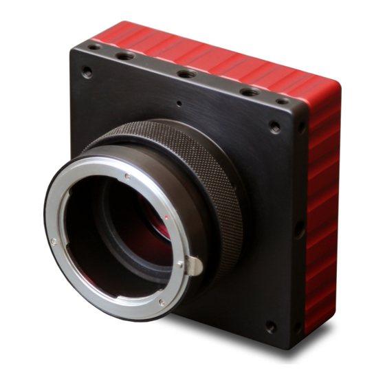
Flare 12M CXP User's Manual 3.12 Lens Control The 12M180 cameras come with support for an optional EF lens mount with integrated lens control. The EF lens mount is connected with a FLARE-EF adapter, shown in Figure 16, and its associated cable, CABFLAREBATT2. Note: The EF lens adapter requires a 12V power supplied by the CABFLAREBATT2 cable connected to the main camera power connector. -
Page 54: Focus
Flare 12M CXP User's Manual 3.12.2 Focus Several registers are used to control lens focus. Table 17 lists the registers and their function. Register Function Lens Control Focus Write 0x1 to set the lens focus to its minimum. Minimum Lens Control Focus Infinity Write 0x1 to set the lens focus to infinity. Lens Control Focus Step Step size for Focus Step commands. -
Page 55: Camera Reset
Flare 12M CXP User's Manual To set the power-up profile write the User Set Default Selector register with a value from 1 to 8 for one of the user profiles or 0 for the factory profile. 3.14 Camera Reset Write a 1 to the Camera Reset register to fully reset a Flare CXP camera. When the reset command is received the camera will reload various settings from memory (serial number, ADC ramp values, etc), reload the bad pixel table, and then load the power up profile. -
Page 56: Order Numbers
Flare 12M CXP User's Manual 4 Order Numbers Table 18 shows the order numbers for Flare 12M180 CXP cameras. Part Number Description 12M180MCX-F Camera, 12MP, monochrome, F-mount, coaxpress 12M180CCX-F Camera, 12MP, color, IR filter, F-mount, coaxpress 12M180CCX-FN Camera, 12MP, color no IR filter, F-mount, coaxpress 12M180NCX-F Camera, 12MP, near IR, F-mount, coaxpress 12M180MCX-C... -
Page 57: Accessories
Flare 12M CXP User's Manual 5 Accessories Table 19 shows the accessories available for Flare CXP cameras. Part Number Description FLAREPWRNA AC Power Adapter (North America) FLAREPWREU AC Power Adapter (Europe) FLAREPWRUK AC Power Adapter (United Kingdom) FLAREPWRIONA AC Power Adapter (North America) with DB9 connector for TTL I/O FLAREPWRIOEU AC Power Adapter (Europe) with DB9 connector for TTL I/O FLAREPWRIOUK... -
Page 58: Document Revision History
Flare 12M CXP User's Manual 6 Document Revision History Revision Date Modification 03/16/15 Initial release. 04/10/15 Update Pixel Format register to match firmware 7 Firmware Revision History Revision Date Modification 03/16/15 Initial release. 04/10/15 Improve Auto Exposure Control. Use GenICam pixel format value for Pixel Format register instead of CoaXPress PixelF value.
Need help?
Do you have a question about the CMOS and is the answer not in the manual?
Questions and answers