Advertisement
Quick Links
Advertisement

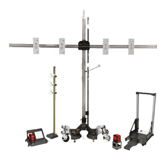
Summary of Contents for John Bean EZ-ADAS
- Page 1 Service Parts Manual EAZ0139L70A Rev. A...
- Page 2 NOTES...
-
Page 3: Service Parts
Service Parts Chapter 3 Service Kits Item Kit Part Number Description EAK0366L09A Vertical Scale Service Kit EAK0366L10A Cross Beam Pivot Service Kit EAK0366L07A No. 4 Target Mount Service Kit EAK0366L06A No. 3 Target Mount Service Kit Kit Instruction Sheets EAK0366L05A No. - Page 4 Service Parts Recalibration Fixtures and Hardware Recalibration Fixtures and Hardware Name / Part Number / Image Target Thumbscrew Pack of 12 EAK0366L12A AS10 Alignment Fixture EAA0496L05AR AS11 Alignment Fixture (use with AS10) EAA0496L15AR AS20 Rear Laser Alignment Fixture EAA0496L07AR AS21 Rear Alignment Fixture EAA0496L12AR...
- Page 5 Service Parts Recalibration Fixtures and Hardware Name / Part Number / Image AT10 Tape Rule Stand EAA0496L09AR Laser Stand EAA0496L06AR Zero Stop EAA0496L13AR Honda Extension Arm Kit (North America) EAA0496L04AR Laser Unit 3-24413A Tape Rule 1-41584A...
- Page 6 Service Parts Recalibration Fixtures and Hardware Name / Part Number / Image T-Handle Quick Lock Pin and Lanyard 8-73437A01 Cross Beam Pivot Bolt 1-05115A Knurled Locking Knob 1-42984A...
- Page 7 Service Parts Front Camera Targets Front Camera Targets **IMPORTANT** Prior to using any of the targets referenced in this document, the user should check the applicable automotive manufacturer’s service information to make certain that the most recently published targets are used. Do not use the targets published in this document if the automotive manufacturer has published targets that are more recent..
- Page 8 Service Parts Front Camera Targets Name / Part Number / Image HON-FC-03 EAK0362L13A (Qty. 1) ® ® HYUNDAI / KIA HYU-FC-01 EAK0362L29A (Qty. 1) ® MAZDA MAZ-FC-01 EAK0362L27A (Qty. 1) MAZ-FC-02 EAK0362L33A (Set - Qty. 2 Pc.)
- Page 9 Service Parts Front Camera Targets Name / Part Number / Image ® MERCEDES-BENZ MB-FC-01 EAK0362L25A (Qty. 1) ® MITSUBISHI MIT-FC-01 EAK0362L32A (Set - Qty. 2 Pc.) ® ® NISSAN / INFINITY NIS-FC-01 EAK0362L30A (Qty. 1) NIS-FC-02 EAK0362L26A (Set - Qty. 2 Pc.)
- Page 10 Service Parts Front Camera Targets Name / Part Number / Image NIS-FC-03 EAK0362L20A (Set - Qty. 2 Pc.) ® ® TOYOTA / LEXUS TOY-FC-01 EAK0362L34A (Qty. 1) TOY-FC-02 EAK0362L23A (Qty. 1) TOY-FC-03 EAK0362L24A (Qty. 1)
- Page 11 Service Parts Front Camera Targets Name / Part Number / Image ® RENAULT REN-FC-01 EAK0362L19A (Qty. 1) ® SUBARU SUB-FC-01 EAK0362L37A (Qty. 1) SUB-FC-02 EAK0362L38A (Qty. 1) ® ® VOLKSWAGEN / AUDI VAG-FC-01 EAK0362L31A (Qty. 1)
- Page 12 Service Parts Rear Camera Equipment Rear Camera Equipment **IMPORTANT** Prior to using any of the targets referenced in this document, the user should check the applicable automotive manufacturer’s service information to make certain that the most recently published targets are used. Do not use the targets published in this document if the automotive manufacturer has published targets that are more recent..
- Page 13 Service Parts Front Radar Equipment Name / Part Number / Image ® ® VOLKSWAGEN / AUDI VAG-RC-01 EAK0362L35A (Set - Qty. 2 Pc.) Front Radar Equipment **IMPORTANT** Prior to using any of the targets referenced in this document, the user should check the applicable automotive manufacturer’s service information to make certain that the most recently published targets are used.
- Page 14 NOTES...
- Page 15 Index...
- Page 16 Instruction Sheets Included EAZ0139L60A Rev. A (EAK0366L01A - Caster Service Kit) EAZ0139L61A Rev. A (EAK0366L02A - Leveling Foot Service Kit) EAZ0139L62A Rev. A (EAK0366L03A - Front Alignment Plate Service Kit) EAZ0139L63A Rev. A (EAK0366L04A - No. 1 Target Mount Service Kit) EAZ0139L63A Rev.
- Page 17 Caster Service Kit EAK0366L01A Rev. A This kit provides the parts and instructions required to replace 3. Remove and discard the existing caster assembly, by removing the four locknuts and carriage bolts securing it a TS100 Target Stand Caster Assembly. to the base assembly.
- Page 18 Leveling Foot Service Kit EAK0366L02A Rev. A This kit provides the parts and instructions required to replace 3. Remove the existing leveling foot assembly, by unthreading the knob from the leveling foot stud and then a TS100 Target Stand Leveling Foot Assembly. unthread the stud from the base plate.
- Page 19 Front Alignment Plate Service Kit EAK0366L03A Rev. A Repair Instructions This kit provides the parts and instructions required to replace a TS100 Target Stand Front Alignment Plate. Removal Contents (See Figure 1 for reference.) 1. Remove the existing front alignment plate, by unthreading See Figure 1 for reference.
- Page 20 Target Mount Service Kit General Safety Information This kit provides the parts and instructions required to replace a TS100 Target Stand Target Mount. Application Risk of personal injury, unsafe conditions and equipment This instruction sheet is used for the Target Mount Service Kits damage.
- Page 21 Cross Beam Service Kit EAK0366L08A Rev. A Contents • F - (2) Hex Head Screw M6 X 70mm • G - (1) Upper Front Mount Bracket See Figure 1 for reference. • H - (1) Hex Head (Pivot) Screw M10 x 30 mm •...
- Page 22 EAK0366L08A Rev. A General Safety Information Installation (See Figure 1 for reference.) The following steps may be competed by first assembling the cross beam as a subassembly on a workbench, and then Risk of personal injury, unsafe conditions and equipment installing it on the mast.
- Page 23 Vertical Scale Service Kit EAK0366L09A Rev. A Contents • D - (6) Hex Lock Nut M6 • E - (2) Slide Bearing See Figure 1 for reference. • F - (1) Scale Bar with Label (0-1695mm) • A - (2) Carriage Bolt M6 X16mm •...
- Page 24 EAK0366L09A Rev. A General Safety Information Installation (See Figure 1 for reference.) 1. Install the replacement slide bearings (E) onto the replacement upper and lower scale brackets (G1, G2), Risk of personal injury, unsafe conditions and equipment using the new self tapping screws (B) provided. Tighten damage.
- Page 25 Cross Beam Pivot Service Kit EAK0366L10A Rev. A Contents • H - (1) Upper Bracket • I - (12) Hex Nut M6 See Figure 1 for reference. • J - (1) Cable Mount Bracket • A - (7) Hex Nut M4 •...
- Page 26 EAK0366L10A Rev. A General Safety Information Risk of personal injury, unsafe conditions and equipment damage. • Before repairing this unit, read this instruction sheet completely. • Follow and perform these instructions as written. • Use the proper personal protective safety equipment and tools as applicable for the work you are performing.
- Page 27 EAK0366L10A Rev. A Pivot Bracket Installation 5. Install the new spirit level (C) to upper mount bracket (H) using two new hex nuts (A). Tighten the hex nuts by hand (See Figures 1 and 4 for reference.) until just tight. Do not overtighten the nuts or you may damage the level.
- Page 28 Winch Service Kit EAK0366L11A Rev. A Contents Repair Instructions Removal See Figure 1 for reference. (As applicable, see Figure 2 for reference.) • A - (4) Lock Nut M6 • B - (1) Winch Assembly 1. Lower the cross beam all the way down, to relieve the tension on the winch cable, then lock the cross beam in •...
- Page 29 EAK0366L11A Rev. A Installation 7. Remove the cover and gear assembly. (See Figure 3 for reference.) 8. Thread the end of the winch cable into the slot in the top of the housing, and then anchor it to the pulley spool using 1.
Need help?
Do you have a question about the EZ-ADAS and is the answer not in the manual?
Questions and answers