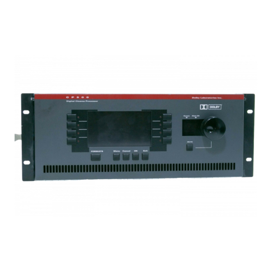
Dolby Laboratories CP500 Reference Diagrams
Hide thumbs
Also See for CP500:
- User manual (8 pages) ,
- User manual (55 pages) ,
- Installation and alignment manual (154 pages)
Table of Contents
Advertisement
Quick Links
!
Information
Model CP500 Cinema Processor
Reference Diagrams
Grounding Details
Installation Wiring
Connector Pin Assignments
System Block Diagram
Card Locations and Signal Flow
Menu Structure
Issue 02
Part No. 91497
S98/11512/12084
Dolby Laboratories Inc.
U.S.A. 100 Potrero Avenue • San Francisco, CA 94103 • Telephone 415-558-0200 • Facsimile 415-863-1373 • Web: www.dolby.com
U.K. Wootton Bassett • Wiltshire SN4 8QJ • England • Telephone +44-(0)1793-842100• Facsimile +44-(0)1793-842101
Dolby and the Double-D symbol are trademarks of Dolby Laboratories
© 1997 Dolby Laboratories Inc.
Advertisement
Table of Contents

Summary of Contents for Dolby Laboratories CP500
- Page 1 U.S.A. 100 Potrero Avenue • San Francisco, CA 94103 • Telephone 415-558-0200 • Facsimile 415-863-1373 • Web: www.dolby.com U.K. Wootton Bassett • Wiltshire SN4 8QJ • England • Telephone +44-(0)1793-842100• Facsimile +44-(0)1793-842101 Dolby and the Double-D symbol are trademarks of Dolby Laboratories © 1997 Dolby Laboratories Inc.
- Page 2 See figure below: To optimize the grounding of the system you must add a jumper between signal ground of the CP500 and the chassis. See figure below: Connection of ground jumper and amplifier...
- Page 3 Most projectors sold in North America come with the new reverse scan LED analog soundhead readers installed. In addition, many existing projectors are being upgraded to include this superior method of playing back SVA soundtracks. The output of the solar cell from this system is at a somewhat lower level than a normal incandescent exciter lamp solar cell.
- Page 6 APPENDIX C BACKPLANE CONNECTORS / REFERENCE DIAGRAMS CP500 Backplane Connector Pin Assignments 1. Automation Connector: Function Number SK1 Format Select Input SK2 Format Select Input SK3 Format Select Input SK4 Format Select Input SK5 Format Select Input SK6 Format Select Input...
- Page 7 4. Bypass / Remote Connector: Signal Name Number Bypass Power Transformer Connection, 16-18 Vac Bypass Power Transformer Connection, 16-18 Vac Remote Control Unit V+ Remote Control Unit Data Remote Control Unit Ground Remote Auditorium Fader + Remote Auditorium Fader Ground 5.
-
Page 8: Mic. Input Connector
7. Optical 1 Input Connector: Signal Name Number Projector 1 Left Channel + Projector 1 Left Channel - Signal Ground Projector 1 Right Channel + Projector 1 Right Channel - Signal Ground Signal Ground 8. Optical 2 Input Connector: Signal Name Number Projector 2 Left Channel + Projector 2 Left Channel -... - Page 9 10. Accessory Rack Analog Connector: Signal Signal Description Number Name AccOptByp Mono input to Cat 682 for Bypass Operation Direct Input to Cat 682 Direct Input to Cat 682 Direct Input to Cat 682 Direct Input to Cat 682 Direct Input to Cat 682 Direct Input to Cat 682 AccSW Ouput to Acc Rack from Cat 662...
- Page 10 11. Accessory Rack Digital Connector: Signal Signal Description Number Name Signal Signal Ground Ground OPTLRCK Left / Right Clock from Optical A/D RETSD2 Serial Data 2 Return RETSD1 Serial Data 1 Return RETSD0 Serial Data 0 Return RETWCK Word Clock Return RETBCK Serial Bit Clock Return ACCBAUD...
-
Page 11: Signal Name
12. 6 Channel Input Connector Signal Name Signal Description Number Signal Ground EXT3 Right Surround Channel External Input Signal Ground Signal Ground Signal Ground Signal Ground Signal Ground Signal Ground Signal Ground Signal Ground Signal Ground Signal Ground Signal Ground EXT0 Left Channel External Input EXT2... - Page 12 13. Reader 1 and Reader 2 Input Connector: Signal Name Signal Description Number TTCO Row Clock Return TCOGND Row Clock Common FTCO Row Clock Send TSCO Pixel Clock Return SCOGND Pixel Clock Common FSCO Pixel Clock Send Differential Video V0 VOGND V0 Common +15VIDEO...
-
Page 14: Signal Paths
CAT.NO. 222SR/A 675A 675A 675A CARD SLOT NUMBERS DIGITAL AUDIO SIGNAL PRESENT LEDS POWER / BYPASS MAIN CP500 RESET BUTTON DIGITAL SUB-SYSTEM POWER INDICATORS RESET BUTTON CAT.NO. +15V -15V J8/J9 SIGNAL PATHS PATH COMMON TO ALL FORMATS 6 Ch D/A Convert/... -
Page 15: Signal Path
CAT.NO. CAT.NO. CAT.NO. CAT.NO. CAT.NO. CAT.NO. CAT.NO. 222SR/A 675A 675A CARD SLOT NUMBERS POWER / BYPASS MAIN CP500 RESET BUTTON POWER INDICATORS CAT.NO. +15V -15V J8/J9 SIGNAL PATH 6 Ch D/A Convert/ Output Level Trim Equalization VCAs Bypass MAIN Optical... - Page 16 CAT.NO. 222SR/A 675A 675A 675A CARD SLOT NUMBERS DIGITAL AUDIO SIGNAL PRESENT LEDS POWER / BYPASS MAIN CP500 RESET BUTTON DIGITAL SUB-SYSTEM POWER INDICATORS RESET BUTTON CAT.NO. +15V -15V J8/J9 PATH COMMON TO SIGNAL PATHS ALL FORMATS 6 Ch D/A Convert/...
- Page 17 CAT.NO. CAT.NO. 675A 675A 675A CARD SLOT NUMBERS DIGITAL AUDIO SIGNAL PRESENT LEDS POWER / BYPASS MAIN CP500 RESET BUTTON DIGITAL SUB-SYSTEM POWER INDICATORS RESET BUTTON CAT.NO. +15V -15V J8/J9 SIGNAL PATHS PATH COMMON TO ALL FORMATS 6 Ch D/A Convert/...
-
Page 18: System Setup Menu Tree
Wakeup More about Format Menu Format Menu LCD Contrast SK 1 SK 1 SK 1 EXIT Trim Format this CP500 SK8 (BACK) Page 2 Page 1 Copy From Decoder OPU Output SK 1 Data Transfer Mono EQ Format Screen Existing... - Page 19 Current Formats Menu Soft Keys: FORMATS MENU Menu SK 1 Selections TO SHEET 1 Menu (SYSTEM SETUP) SK 3 EXIT Diagnostics PASSWORD PROTECTED EXIT Menu Alignment Menu B-Chain Noise SK 1 Sequence B-Chain Select Channel Optical Output Adjust Alignment Surround Set Dolby L, C, R, Ls, Rs, Sw Reversion...


Need help?
Do you have a question about the CP500 and is the answer not in the manual?
Questions and answers