Table of Contents
Advertisement
Quick Links
Advertisement
Table of Contents

Summary of Contents for Chell CCD100
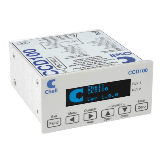
- Page 1 Chell Instruments Ltd Folgate House Folgate Road North Walsham Norfolk NR28 0AJ ENGLAND Tel: 01692 500555 Fax: 01692 500088 Chell Configurable Display CCD100 OPERATING MANUAL info@chell.co.uk e-mail:- Visit the Chell website at: http://www.chell.co.uk 900219-1.0...
- Page 2 Chell Document No. : 900219 Issue 1.0 ECO: ---- Date: 20 February 2018 Chell’s policy of continuously updating and improving products means that this manual may contain minor differences in specification, components and circuit design from the actual instrument supplied.
-
Page 3: Table Of Contents
INDEX SECTION 1 - INSTRUMENT OVERVIEW ..................2 SECTION 2 - SPECIFICATION ....................... 3 2.1 P : ........................... 3 OWER UPPLY 2.2 O : ......................3 PERATING CONDITIONS 2.3 M : ..................... 3 EASUREMENT AND UTPUTS SECTION 3 - INSTALLATION AND INTERCONNECTIONS ............4 3.1 T - 15 W 'D' T... - Page 4 PPENDIX 9.2 A B ..........................29 PPENDIX 9.3 A C ..........................30 PPENDIX TABLES Table 1 – CCD100 Command Set Summary ..............28 Table 2 – Factory Defaults ....................29 Table 3 – Settings in ‘ras’ command string ..............30...
-
Page 5: Section 1 - Instrument Overview
This is the third generation of the Chell CCD100 display. The CCD100 is a single channel unit which can be used to operate a flow controller or display the output from a pressure transducer. It supports both voltage transducers (typically 5 &... -
Page 6: Section 2 - Specification
Section 2 - Specification Power Supply: Line voltage: 24V DC. ±5% Consumption: less than 500mA Protection: Internal resettable fuse Operating conditions: Operating temperature range: +5°C to +50°C (40°F to 122°F) Storage temperature range: -20°C to +70°C (-40°F to 158°F) Maximum Relative humidity: 95% at 50°C (non condensing) Warm up time to full accuracy: 15 minutes (assumes unit already stabilised at... -
Page 7: Section 3 - Installation And Interconnections
Note that the instrument must always be situated in such a way as to enable adequate air circulation about the unit. If a transducer was supplied with the CCD100 a suitable cable may have been included. Transducer socket Pinout - 15 Way 'D' Type... -
Page 8: Usb Connector - Usb Type-C
CCD100 should be protected by fuse or other suitable electronic method. A standard 5mm diameter ‘dc power jack’ is required to connect to the CCD100. Connect the positive conductor to the centre pin. Connect the negative (0V) conductor to the outer of the jack. -
Page 9: Section 4 - Front Panel Operation
Section 4 - Front Panel Operation Introduction The front panel consists of a 128x32 pixel monochrome graphic OLED display with 6 membrane key switches below it. Each switch has legends on and above or below it to indicate its function under different conditions, although there are certain common functions to each screen, as detailed below. -
Page 10: Hmi Breakdown
Zero Perform input rezero (if held for 3 seconds) By default the Func switch does nothing, but special builds of the CCD100 may include functionality for this switch. In such cases an addendum to this manual will indicate the function. -
Page 11: (C) Main Screen (Setpoint Valve Control)
Special note for millivolt option: If the millivolt option is fitted, then the command output is used as the excitation source for the transducer. As such the SP: will change to EXP: to indicate that the user is controlling the excitation output. -
Page 12: (D) Main Menu Screen
The Main Menu screen allows the user to select screens that are used for the configuration of the CCD100 – the setpoint (initial value, initial mode, source), input (range, full scale, units string), comms, filtering and relays can all be configured from screens selected via the main menu. -
Page 13: (F) Input Screen
Special note for millivolt option: If the millivolt option is fitted, the only configurable item here is the initial excitation value. Switch Functions: Func Go back to Main Menu screen Select previous character when in edit mode ◄ Select next character when in edit mode ►... -
Page 14: (G) Comms Screen
(g) Comms Screen The IP address and the subnet mask of the device can be changed here. The device will need to be reset to enact these changes. Switch Functions: Func Go back to Comms Menu screen ◄ Go to previous menu selection ►... -
Page 15: (I) Relay Screen
If Factory Defaults is selected from the Main Menu, this screen appears to ask for confirmation of the requested function. If confirmed then the screen changes to show a percentage of completion of the factory defaults and once completed the CCD100 will restart. Switch Functions: Func... -
Page 16: Section 5 - Webserver
Section 5 - Webserver Main page The Web server can be used by entering the IP address of the device into a browser address bar. This allows the user control of various settings within the device, and to read the devices current reading. Along the top are a series of tabs to allow the user to switch to various sections of device control. -
Page 17: Channel Configuration Page
Channel Configuration page The channel configuration contains channel setup options. · Units string allows the user to change the units of the channel. · Range is the Engineering unit conversion of the Voltage output from the transducer (e.g. in the image above 10 Volts = 100 mbar). -
Page 18: (A) Communication
(a) Communication The communication page allows the user to change the IP address and Subnet mask of the device. Obviously no octet in the IP Address or Subnet mask can be set to higher than ‘255’. Once applied the device will need to reset, so the communications page will show a pop- up (see below) that prompts the user to refresh. -
Page 19: Section 6 - Serial & Tcp Communication
Section 6 - Serial & TCP Communication Introduction The CCD100 allows full control and feedback via TCP/IP and RS232 (via the USB port). All controls via the HMI are also available via comms or on the webserver and all calibration is also performed via comms commands or the webserver. -
Page 20: Main Commands
The <setpoint mode> is a single number that represents the current mode of the setpoint: 0 = Auto, 1 = Open, 2 = Closed. This number is mainly included for use with Chell’s front- end software (DisplayX) and is mainly useful when outputting repeated readings, where it effectively provides a constant update of the current mode of the setpoint. -
Page 21: (B) Output Current Readings Repeatedly - 'Rp
(b) Output current readings repeatedly – ‘rp’ The CCD is also able to report the current readings repeatedly, at a given interval. This command starts and stops this repeat activity by setting the parameter accordingly: 0 = Repeat off 1 = Repeat every 100ms 2 = Repeat every 500ms 3 = Repeat every second 4 = Repeat every minute... -
Page 22: (E) Setpoint Source - 'Sps
(e) Setpoint source – ‘sps’ The setpoint source can be an internally set value or a percentage of the secondary CCD input (known as slave input). This source is set using this command and as with the other setpoint commands, it takes just one parameter which is as follows: 0 = Internal source 1 = Slave source (For more information on setpoint sources, see the Principles section - 7.4(b)). -
Page 23: Comms Commands
Comms commands (a) Ethernet IP address – ‘eip’ This command changes the IP address used to communicate over TCP/IP comms. The parameter should be entered as a standard 4 octet IP address. e.g. 192.168.1.180. The max octet value is obviously 255. If a greater value is entered, that value will be capped to 255. -
Page 24: Channel Setup Commands
Channel Setup commands (a) Input channel units string – ‘uiu’ The input channel has an associated free-form text field that can be used to identify the units being used. This command is used to set this and its only parameter is a max of 5 characters for the units string. -
Page 25: Filtering Commands
Filtering commands (a) Filter band – ‘flb’ This command is used to set the point at which the adaptive filtering kicks in. It takes one parameter which is the percentage of full scale of the input. Valid values are between 0.01% and 1.00%. -
Page 26: (B) Relay Hysteresis - 'Rlh
(b) Relay hysteresis – ‘rlh’ This command configures the hysteresis setting of the relay. It takes two parameters – the first if the relay in question, the second is the percentage hysteresis, represented as a percentage of full scale of the source channel, with limits of 0.0% (i.e. no hysteresis) to 10.0%. -
Page 27: Section 7 - Principles
Section 7 - Principles Introduction This section describes the principles used in the CCD100. It details the various settings for the inputs and the outputs including setpoint control. It does not detail any servicing or calibration procedures. Analogue Inputs The CCD100 has two analogue voltage input channels. The main input can be configured to accept any input voltage from 0V to a full scale of up to 10V. -
Page 28: Setpoint Control
Setpoint Control As mentioned above, there is one analogue output that is used for command setpoint control that can be used to operate a mass flow controller or similar. The setpoint command output has a voltage full scale that matches the input channel configuration. Example If the input channel is setup for a 100 slpm 5V full scale device, and the setpoint value is 10.0 (assuming setpoint is in Auto mode and not a slave source), then the output voltage... -
Page 29: Adaptive Filtering
Adaptive Filtering The CCD100 includes an adaptive averaging filter on the display and comms readings output to aid in ‘smoothing out’ unwanted ‘noise’ on the displayed readings. (a) Operational band The filter can be configured to only operate within a certain band, meaning that excursions between subsequent readings that fall outside that band are shown as real (and not filtered) readings. -
Page 30: Section 8 - Service And Calibration
Section 8 - Service and Calibration Service There are no user serviceable parts inside the instruments. Should any difficulties be encountered in the use of the CCD100, it is recommended that you contact Chell Instruments Ltd for advice and instructions. Calibration There is no user calibration for the CCD100. -
Page 31: Section 9 - Appendices
Section 9 - Appendices Appendix A Table 1 – CCD100 Command Set Summary Purpose Query Parameters Notes Output current readings Output current P1: 0 = Repeat off readings repeatedly 1 = Repeat every 100ms 2 = Repeat every 500ms 3 = Repeat every second... -
Page 32: Table 2 - Factory Defaults
Appendix B Table 2 – Factory Defaults Setting Default Value Additional Information Repeat Rate (for output readings) Repeat off Ethernet IP Address 192.168.1.180 Ethernet Subnet Mask 255.255.255.0 Input Channel Units String “” No units strings set Input Channel Range 10.000 Input Channel Full Scale * If millivolt option fitted 10.000 (V) or... -
Page 33: Table 3 - Settings In 'Ras' Command String
Appendix C Table 3 – Settings in ‘ras’ command string Description Type and size Input channel units string 5 char string range 8 char string representation of a float full scale 8 char string representation of a float Setpoint value 8 char string representation of a float slave value 8 char string representation of a float...
Need help?
Do you have a question about the CCD100 and is the answer not in the manual?
Questions and answers