Advertisement
Quick Links
Advertisement

Summary of Contents for Force USA F-F50
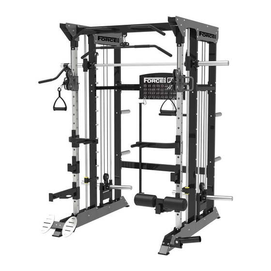
- Page 1 USER MANUAL | F-F50...
-
Page 2: Assembly Manual
ASSEMBLY MANUAL BEFORE YOU START Read all instructions in this manual before assembling or using this equipment. Remove all parts from the packaging and separate and count each various component to ensure everything has been correctly provided. Follow the instructions and consult both the individual assembly pages and the overall expanded views of the equipment. -
Page 3: Important Assembly Information
IMPORTANT ASSEMBLY INFORMATION NOTE: It is strongly recommended that this equipment is assembled by two or more people to avoid possible injury. Tools Required for Assembling the Bench: Adjustable Wrench and Allen Wrench. Ensure Carriage Bolts are inserted through the SQUARE holes on components that need to be assembled. - Page 4 ASSEMBLY MANUAL Parts list-1 (individual packaging) Base welding Rear riser assembly*2 Center column NO 1 NO 2 NO 3 sets*2pcs assembly* 2pcs Optical axis fixing Middle connection NO 4 Top component*2pcs NO 5 NO 6 group*2pcs components*1pcs Upper beam Lower connection Functional trainer NO 7 NO 8...
- Page 5 Left safety welding Left parallel bar welding Left safety welding set NO 16 NO 17 NO 18 set*1pcs group *1pcs *1pcs Parts list-2 (individual packaging) Right parallel bar Lifting welding Low pull welding NO 19 NO 20 NO 21 welding group*1pcs group*1pcs group*1pcs Left Smith Insurance...
- Page 6 Parts list-3 (assembly parts) NO 31 Right upper cover *2pcs NO 32 Left upper cover*2pcs NO 33 Right lower cover *2pcs NO 34 Left lower cover*2pcs NO 35 Label board *1 NO 36 Wire rope*2 pieces Olympic Chrome Stainless steel conduit Smith optical axis NO 37 NO 38...
- Page 7 Parts list-4 (assembly parts) Stainless steel butterfly No.49 Chain 0.35m*2 pieces No.50 T type bolt *1 No.51 clip *2 Weight piece rubber No.52 Triceps press rope *1 No.53 No.54 Blister pack*2 sleeve * 4 pieces Blister pack screw schedule-5 (standard parts) Hexagon socket flat Hexagon socket flat Hexagon socket flat head...
-
Page 8: Assembly Steps
Assembly steps project Steps Name Name number No.1 Base welding group Tools/equipment Put two base welding group on the ground, keep in same direction and 1.2m distance... - Page 9 Assembly steps project Steps Name Name number No.2 Rear riser assembly M10*60 hexagon socket flat head screws Ø10 flat gasket M10 lock nut Tools/equipment No. 6 hexagon socket screwdriver, wrench Put the Rear riser assembly on the base as shown in the picture, pay attention to the upper and lower ends.
- Page 10 Assembly steps project Steps Name Name number Middle connection No.6 components M10*100 hexagon socket flat head screws Ø10 flat gasket M10 lock nut Tools/equipment No. 6 hexagon socket screwdriver, wrench Install the connecting components as shown in the figure, paying attention to the installation direction of the riveting surface.
- Page 11 Assembly steps project Steps Name Name number Lower connection No.8 components M10*100 hexagon socket flat head screws Ø10 flat gasket M10 lock nut Tools/equipment No. 6 hexagon socket screwdriver, wrench Install the connection components as shown...
- Page 12 Assembly steps Project Steps Name Name Number No.3 Center column assembly M10*20 hex socket flat head screw Tools/equipment No. 6 hexagon socket screwdriver Install the center column assembly as shown in the figure, paying attention to the upper column. and lower ends of the center...
- Page 13 Assembly steps project Steps Name Name number No.4 Top component M10 lock nut M10*60 hexagon socket flat head screws M10*20 hex socket flat head screw Ø10 flat gasket Tools/equipment No. 6 hexagon socket screwdriver, wrench Install the top parts as shown in the figure, do not tighten the screws temporarily, just hang them, so as to facilitate the later assembly of other accessories...
- Page 14 Assembly steps project Steps Name Name number Optical axis M10*60 hexagon socket No.5 flat head screws fixing group M10*25 hexagon No.40 Small door optical axis socket head screw Weight piece No.53 Ø10 flat gasket rubber sleeve Pulley with No.25 M10 lock nut reorganization Barbell bar No.30...
- Page 15 Assembly steps project Steps Name Name number Optical shaft sleeve Smith Insurance Group No.13 No.24 welding group Right No.39 Smith Optical Axis No.46 Bottom nylon sleeve No.48 Insurance guide set Smith Insurance Group No.23 Left Tools/equipment The left and right Smith optical shafts are assembled in the same way. Please distinguish between No. 23 and No.
- Page 16 Assembly steps project Steps Name Name number Sliding sleeve Cross set No.9 Ø10 flat gasket right Sliding sleeve Cross set No.10 M10 lock nut Left No.38 Stainless steel conduit M10*70 hexagon socket flat head screw Tools/equipment No. 6 hexagon socket screwdriver, wrench The lettering surfaces of the regulating tube are installed facing inwards, the lettering sequence is from bottom to top, and the left and right adjustment groups are assembled in the same way.
- Page 17 Assembly steps project Steps Name Name number Recommended combination package M10*20 hex socket flat head screw M10 lock nut Ø10 flat gasket Tools/equipment No. 6 hexagon socket screwdriver, wrench Install the recommended combination as shown.
- Page 18 Assembly steps project Steps Name Name number No.36 Cable No.44 Rubber cover No.41 Standard safety hook No.45 Small aluminum cap No.42 Low pull handle No.43 Card slot set Tools/equipment No. 4 6 hexagon socket screwdriver, wrench Note that the two ends of the wire rope are divided into large and small ends, pay attention to the direction of the joint, and remove the two pulleys at the bottom of the base when threading.
- Page 19 Assembly steps project Steps Name Name number No.31 Upper guard plate right M10 lock nut No.32 Upper guard plate left M10*100 hexagon socket flat head screws Ø10 flat gasket Tools/equipment No. 6 hexagon socket screwdriver, wrench As shown in the figure, please note that no screws are installed in the two holes marked, which are reserved for the next installation of the beam.
- Page 20 Assembly steps project Steps Name Name number No.7 Upper beam assembly M10*100 hexagon socket flat head screws Ø10 flat gasket M10 lock nut Tools/equipment No. 6 hexagon socket screwdriver, wrench As shown in the picture, install the upper beam assembly.
- Page 21 Assembly steps project Steps Name Name number No.35 Label board M10*20 hex socket flat head screw Tools/equipment No. 6 hexagon socket screwdriver Note that the hook of the sticker plate is installed inward.
- Page 22 Assembly steps project Steps Name Name number Barbell bar welding No.12 group No.47 Sheath M10*20 hex socket flat head screw Tools/equipment No. 6 hexagon socket screwdriver As shown in the picture, install the barbell rod welding parts...
- Page 23 Assembly steps project Steps Name Name number Parallel bar welding No.14 Hook welding group left No.18 group left Hook welding group Parallel bar welding No.15 No.19 right group right Insurance welding group No.16 left Insurance welding group No.17 right Tools/equipment Pay attention to the installation of the module and the direction of rotation after installation.
- Page 24 Assembly steps project Steps Name Name number No.33 Lower guard plate right M10 lock nut No.34 Lower guard plate left M10*100 hexagon socket flat head screws Ø10 flat gasket Tools/equipment No. 6 hexagon socket screwdriver, wrench Pay attention to distinguish the left and right guard plates, as shown in the figure, the large hole guard plate is on the outside.
- Page 25 Assembly steps project Steps Name Name number Ground Cannon M10*60 hexagon socket No.26 Combination flat head screws M10*20 hex socket flat No.28 Hook tripod group head screw No.29 Low pull pedal group No.50 T type bolt Tools/equipment No. 6 hexagon socket screwdriver Install other components as shown in the figure.
- Page 26 Assembly steps project Steps Name Name number No.20 Lifting welding group No.21 Low pull welding group High tensile welding No.22 group No.27 Push rod welding group Tools/equipment As shown in the figure, part of the unassembled parts and parts that are not used in the movement are hung on the label board to complete all assembly.
-
Page 27: Warranty
It comes from the urge to push boundaries and break through barriers. We know this because we’ve been there from selling the first piece of Force USA gear in 2007 to providing commercial and home gym equipment all over the globe. We are for helping you become your strongest self.
Need help?
Do you have a question about the F-F50 and is the answer not in the manual?
Questions and answers