Table of Contents
Advertisement
Quick Links
Installation Manual
®
Con TROLL
PRO Installation Manual
Information subject to change without notice. In-Situ, In-Situ logo, Baro Merge, BaroTROLL, HERMIT, HydroVu™, iSitu, Pocket-Situ, RDO,
©
RuggedCable, RuggedReader, SmarTROLL™, TROLL, VuSitu, and Win-Situ are trademarks or registered trademarks of In-Situ Inc.
2009-
0085660 | 2018-08-23
2013. All rights reserved. This product may be covered by patents identified at www.in-situ.com/patents
Advertisement
Table of Contents

Subscribe to Our Youtube Channel
Summary of Contents for In-situ Con TROLL PRO DC-L
- Page 1 ® Con TROLL PRO Installation Manual Information subject to change without notice. In-Situ, In-Situ logo, Baro Merge, BaroTROLL, HERMIT, HydroVu™, iSitu, Pocket-Situ, RDO, © RuggedCable, RuggedReader, SmarTROLL™, TROLL, VuSitu, and Win-Situ are trademarks or registered trademarks of In-Situ Inc. 2009- 0085660 | 2018-08-23 2013.
- Page 2 Apple Inc., registered in the U.S. and other countries. The Bluetooth word mark and logos are registered trademarks owned by the Bluetooth SIG, Inc. and any use of such marks by In-Situ Inc. is under license. NIST is a registered trademark of the National Institute of Standards and Technology, U.S.A.
-
Page 3: Table Of Contents
Table of Contents 1 Safety Hazard Symbols that Appear in the Manual Precautionary Labels that many Appear on the Product 2 Overview Available Models Compatible Instruments Box Contents 3 Mounting the Controller Optional Mounting Kit Mounting Options Controller Dimensions Pole Mounting Wall Mounting Using Mounting Tabs Wall Mounting with User-supplied Hardware DIN Rail Mounting the Enclosure... - Page 4 Replacement Desiccant Replacement Clock Battery User-Serviceable Parts 8 Specifications Overview Specifications 9 Declaration of Conformity...
-
Page 5: Safety
Safety Please read this manual before unpacking or installing any part of this system. Hazard Symbols that Appear in the Manual Danger—Indicates a hazardous situation, which, if not avoided, will result in death or serious injury. Note—Indicates a situation that is not related to potential injury. Les Symboles D'advertissement Figurant Dans Le Guide Danger—indique une situation dangereuse, qui, si elle n'est pas évitée, pourra provoquer la mort ou des blessures sérieuses. -
Page 6: Overview
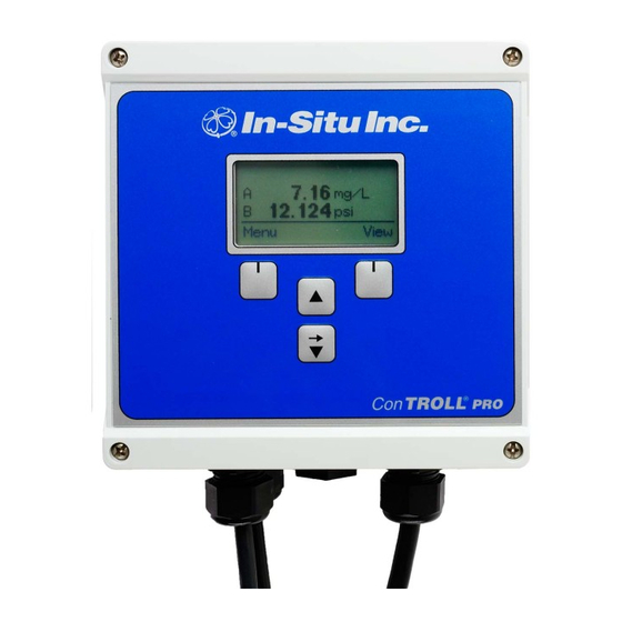
Overview All Con TROLL PRO models contain the following items. NEMA 4X rated Robust keypad and display window Easy-to-use controller software For a complete list of controller specifications See "Specifications" on page 32 Available Models The Con TROLL PRO is available in three models. Model DC-L, a battery- or solar-powered controller with logging abilities. -
Page 7: Box Contents
Box Contents Remove the controller from the shipping box. The shipping box should contain the following items. Controller (1) Controller plugs (5) Dome connectors (3) O-rings (6) Large lock nuts (6) Sealed desiccant pack (1) that will be placed in the installed controller. Opened desiccant pack (1) that protected the instrument during shipping. - Page 8 Figure 2.2 Internal view of AC model...
-
Page 9: Mounting The Controller
Mounting the Controller Danger—Only properly trained and qualified personnel should install the controller described in this manual. This instrument should be installed for use in non-hazardous locations only. Danger—L'installation de l'appareil “controller” décrite dans le guide d'utilisateur doit impérativement être réalisée par des personnes qualifiées. -
Page 10: Mounting Options
Mounting Options Controller Dimensions Figure 3.2 shows the controller dimensions with the lid closed. Figure 3.3 shows the dimensions of the controller box with the lid open. It indicates where holes should be drilled for wall or panel mounting without using the supplied mounting tabs. Figure 3.4 shows the depth dimensions of the controller. - Page 11 Figure 3.3 Controller dimensions with lid open...
- Page 12 Figure 3.4 Side view dimensional drawings...
-
Page 13: Pole Mounting
Pole Mounting 1. Remove the 4 nuts and 4 screws from the mounting kit. 2. With the enclosure open, drop 1 nut into each drilled corner of the box. 3. Use a screwdriver to push the nut down and set it in place. Figure 3.5 Placing the nut in the enclosure 4. -
Page 14: Wall Mounting Using Mounting Tabs
Figure 3.6 Attaching the mounting brackets Figure 3.7 Back and side view of pole-mounted controller Wall Mounting Using Mounting Tabs The optional mounting kit contains a set of wall mounting hardware that includes four screws, nuts, and tabs for mounting the controller to a wall or panel. - Page 15 Figure 3.8 Back view of controller with tabs...
-
Page 16: Wall Mounting With User-Supplied Hardware
Wall Mounting with User-supplied Hardware You can supply your own mounting hardware and attach the controller to a wall. Use a screw that is best suited for your wall material. Figure 3.9 Back view of Con TROLL PRO... -
Page 17: Din Rail Mounting The Enclosure
Figure 3.10 Template for wall mounting with user-supplied hardware DIN Rail Mounting the Enclosure Each rail mount clip is secured to the enclosure with a supplied #6 screw. 1. With the enclosure open, drop 1 screw into each drilled corner of the box. 2. -
Page 18: Placing Dome Connectors And Plugs In The Enclosure
Figure 3.11 Placing the screw in the enclosure Figure 3.12 Securing the screw to the DIN clip Placing Dome Connectors and Plugs in the Enclosure When installed as directed, this product is rated IP-67 and can withstand temporary immersion in up to 1 meter of water. To meet the IP-67 rating, the following conditions must be met. - Page 19 Do not over tighten. 5. Thread sensor or electrical cables through the dome connectors for later wiring by a qualified electrical technician. Tighten to approximately 15 in-lbs of torque. Figure 3.13 Controller box hardware Figure 3.14 Attached port plug (left) and attached dome connector (right)
-
Page 20: Electrical Connections
Electrical Connections Danger—Only properly trained and qualified personnel should install the controller described in this manual. This instrument should be installed for use in non-hazardous locations only. Danger—L'installation de l'appareil “controller” décrite dans le guide d'utilisateur doit impérativement être réalisée par des personnes qualifiées. - Page 21 Make sure that each wire is stripped-and-tinned to .025 in. Make sure that each wire is tightly screwed into the terminal strip. Make sure that each wire is touching the terminal strip. If the plastic wire jacket is clamped into the terminal strip, connections will not be made.
-
Page 22: Relay Connections
Figure 4.2 AC circuit board and terminal connections 1. Disconnect power to the controller. 2. Use a Phillips screwdriver to remove the controller lid. 3. Use a Phillips screwdriver to remove the AC board cover. 4. Carefully pull the cover out of the enclosure. 5. -
Page 23: Disconnecting Ac Power
Connexions Aux Relais Danger—Débrancher toute alimentation à l'appareil avant de connecter les fils. Danger—Ne pas connecter des circuits basse tension (moins de 50 V) aux bornes de connexion sur la carte électronique de secteur (courant alternatif)! 1. Disconnect power to the controller. 2. -
Page 24: Input/Output Connections
Input/Output Connections The Input/Output board is shown in Figure 5.1 . It is located inside the enclosure on the left side. Refer to the individual probe manuals for wiring diagrams. Also refer to the Con TROLL PRO Operator’s Manual. Figure 5.1 Input/Output board and required wire types Do not over tighten the screws on the terminal block. -
Page 25: Sensor Wiring Connections
Danger—Débrancher toute alimentation à l'appareil avant de connecter les fils. Before attaching the In-Situ sensors, make sure that their communication settings are set to the factory default values. If you have a new sensor, these are already set. If you are using an existing sensor, use Win-Situ 5 Software to reset the communication settings. -
Page 26: Current Loop Outputs
5. Replace the controller lid and tighten screws. 6. Reconnect power to the device. If you want to use RuggedCable with twist-lock connectors, order a short length of stripped-and- tinned RuggedCable with a male connector. This can be wired into the controller, then connected to existing twist-lock cable connectors. - Page 27 To positive (+) end of LOOP1+ customer-supplied device Green earth ground Shielded wire (silver color) screw 4. Connect the wires at the device end. Do not ground the device at both ends of the cable. 5. Replace the controller lid and tighten screws. 6.
-
Page 28: Relay Connections On The I/O Board
Relay Connections on the I/O Board Please note that the DC and AC models have different types of relays available. All relay connections are unpowered relay NC & NO contact connections only. DC Models Low-voltage relays are available through the I/O board only. AC Models Low-voltage relays are available through the I/O board. -
Page 29: Optional Battery Box
Optional Battery Box Overview of Battery Box Kit The optional external battery box kit is designed to power the DC-L Model Con TROLL PRO via battery. It may also be used in conjunction with a 10W or 20W solar panel. The kit contains the following items. -
Page 30: Connect The Battery Terminals
Connect the Battery Terminals 1. Place the batteries in the enclosure as shown. 2. Connect the black (–) leads to the black terminals. 3. Connect the red (+) leads to the red terminals. Upon connection of the red leads, you should notice that the controller screen illuminates. Figure 6.1 Internal components of the battery box... -
Page 31: Maintenance
6. Reconnect power to the device. User-Serviceable Parts This device contains no user-serviceable electronic parts. For information regarding service or returns, contact the In-Situ Customer Service Technicians. U.S.A. and Canada at 1-800-446-7488, option 3 Internationally at 1-970-498-1500 In-Situ Inc. Attn: Customer Service Department 221 E. -
Page 32: Specifications
Specifications Overview The Con TROLL PRO has an easy-to-use interface that supports 2 probes. AC and DC versions are available. The DC version is low-power-consumption data logger with local display and communication gateway for groundwater or surface water probes. The AC version is a line-powered process controller with optional logging functions, plus local display and communication gateway features forIn-Situ Inc. -
Page 33: Declaration Of Conformity
Declaration of Conformity...
Need help?
Do you have a question about the Con TROLL PRO DC-L and is the answer not in the manual?
Questions and answers