Table of Contents
Advertisement
Quick Links
Advertisement
Table of Contents

Summary of Contents for POWERSYS ERT-200S
- Page 1 Feeder Remote terminal Unit ERT-200S Manual www.powersys.kr...
-
Page 2: Table Of Contents
Load Break Switch Control ERT-200S CONTENT Product Introduction ......................6 1.1. Introduction RTU ..........................6 1.2. Features ............................... 7 Technical Specification ......................9 2.1. Control General Specification ......................9 2.2. Environment Condition ........................10 2.3. FRTU TECHNICAL SPECIFICATION ....................11 2.4. - Page 3 Load Break Switch Control ERT-200S 4.4. Remote Communication Port ....................... 25 4.5. Digital Input /Output ........................26 4.6. DOOR Port ............................26 4.7. AUX. DI/DO ............................26 4.8. Motor Output Port ......................... 26 4.9. Power Supply Input (AC Input) ....................26 4.10.
- Page 4 Load Break Switch Control ERT-200S 6.2. Cold load PickUp ..........................46 6.3. Operation of Inrush ........................47 6.4. SEF (Sensitive Earth Fault) Detection ..................47 6.5. Role of the Sectionalizer(Auto Sectionalizing) ................. 48 6.6. Phase Loss Detection ........................49 6.7. Phase Sync. Check........................... 49 Operation Setting ........................
- Page 5 Load Break Switch Control ERT-200S 8.2. Status view ............................90 8.3. Counter view ............................ 91 8.4. Alarm View ............................91 This menu displays controller Fault detection..................91 8.5. System Information ........................92 Event (Event Log) ........................93 Appendix 1. Drawings ........................96...
-
Page 6: Product Introduction
1. Product Introduction 1.1. Introduction RTU ERT-200S is embedded in Distribution Automation SF6 gas insulated load break switch (Pole mount) control box. It receives measurement information (3 phases current & voltages) and status information from Switch, and meters current and voltage, detects FI, Line cut, Live line/Dead line, Unbalance,Sectionalizeroptimizedfor remote control and automation systems. -
Page 7: Features
Load Break Switch Control ERT-200S 1.2. Features Magnitude and phase angle of voltages & currents Sequence components of 3-Phase voltages & currents True RMS of voltages & currents Active, reactive and apparent power for each phase and ... - Page 8 Load Break Switch Control ERT-200S Switch Open/Closed/Select Mechanical Locked Gas Pressure Low External AC Power Status LBS Door Open Monitoring Battery Low Local/Remote Fault Indication Open Line Detection Event recording with time stamp •...
-
Page 9: Technical Specification
Load Break Switch Control ERT-200S 2. Technical Specification This section details the technical specifications of the Load Break Switch (LBS) and Control System. Provide to detail setting values of timing, current, voltage and other measurement accuracy is given 2.1. Control General Specification... -
Page 10: Environment Condition
Load Break Switch Control ERT-200S 2.2. Environment Condition Environmental condition <2,000m Altitude 40m/s Wind Speed CT Input, VT Input, Control Power Input, Fiber- optic insulation Input and Relay output Dielectric Strength AC 60㎐, 2㎸/1 minute IEEE C62.45 (1992) , 6㎸(1.2×50㎲), 3㎄(8×20㎲) of ... -
Page 11: Frtu Technical Specification
Load Break Switch Control ERT-200S 2.3. FRTU TECHNICAL SPECIFICATION FRTU Technical Specification 50 / 60 Hz System Frequency AC Voltage Power : 16Vac/32Vac Power Input Modem : DC 24V Max : 1A Power Output Current Transformer Input Current Input IA,IB,IC,IN,ZCT (Max : 13A) ... -
Page 12: Analog/Digital Conversion
Load Break Switch Control ERT-200S Serial Port Peripherals : 2 CAN / 3 SCI(UART) / • 2 McBSP / 1 SPI / 1 I2C 2.4.2. Analog/Digital Conversion ADC Feature 16 Bit A/D Converter Anti-aliasing analog filter One gain channel for each current input : ... -
Page 13: Function Blockdiagram
Load Break Switch Control ERT-200S 2.5. Function BlockDiagram... -
Page 14: Fault Detect And Sectionalizing Functions
Load Break Switch Control ERT-200S 2.6. Fault Detect and Sectionalizing Functions Phase Fault Detection Phase Fault Threshold Current Setting Range 5 to 900A (Pick up Current) Default : 400A / step : 1A Definite Time for Fault to Persist Setting Range 0.01 to 10.0 sec... - Page 15 Load Break Switch Control ERT-200S 1~180 s FI Reset Time Default : 20s / step : 1s Line Open Detection 50 ~ 90 % Live Line ON Voltage Setting Range Default : 50% / step : 1% 35 – 75%...
-
Page 16: Power System Measurements
Load Break Switch Control ERT-200S OFR (Over Frequency Relay) 50.00 to 70.00 Hz Over Frequency Pickup Level Default: 62.20Hz/step : 0.01Hz 50 ~ 85% Pick up Voltage Setting Range Default : 80% / step : 1% 0.1 ~ 20.0 sec Delay Time Setting Range Default : 1.0s / step : 0.1s... -
Page 17: System Setting
Load Break Switch Control ERT-200S Frequency Measurement Reading range 10 ~ 100Hz Accuracy ±0.1Hz Energy measurement Reading range 0 ~ 65565 Accuracy ±2% Average Demand Current and Power Configurable demand interval Ia, Ib, Ic, Pa, Pb, Pc, P3ph, 15minutes Daily max. currents and power are stored 2.8. -
Page 18: Communications
Load Break Switch Control ERT-200S 2.9. Communications RS232C DCD(1), Rx(2), Tx(3), DTR(4), GND(5), DSR(6), 9pin Signals TRS(7), CTS(8), NC(9) Speed(Baud rate) 1200,2400,4800,9600,19200,38400 CTS,DCD signal Timeout Configurable Modem Control RTS off-delay Configurable DNP3.0 / DNP-TCP Support DNP3.0 Subset Level 2 ... - Page 19 Load Break Switch Control ERT-200S Communication DNP, IEC60870-5-101, IEC60870-5- Protocol Setting Protocol Select 104, DNP/TCP Default : DNP 1200/2400/4800/9600/19200 Comm. Speed Default : 9600pbs Comm Line 2Wire/4Wire / Default : 2Wire Modem Control RTS Off Delay 10 ~ 500ms / Default : 10 ms...
- Page 20 Load Break Switch Control ERT-200S M_ME Address 1-10000 / default : 1000 C_SE Address 1-10000 / default : 2000 M_IT Address 1-10000 / default : 4000 LINK Address 1-254 / Default : 1 ASDU Address 1-254 / Default : 1...
-
Page 21: Event Record
System Event Status Change of System ➔ System Reset ➔ Set Change ➔ Communication Error ➔ AC Loss Control Event Controlled status of ERT-200S ➔ SW Control ➔ Control ➔ Locked ➔ FI Reset ➔ Battery test Measure Event Measure status of ERT-200S 1) Average 15 ➔... - Page 22 Load Break Switch Control ERT-200S Waveform Event Record Event List Description Waveform Waveform Recording • Storage:8 Fault Waveforms of 10 cycles. Sampling ratio : 32 Sample/Cycle * 10 Cycles Max 8 fault waveforms can be captured on non-volatile memory...
-
Page 23: Physical Description
Load Break Switch Control ERT-200S 3. Physical Description The ERT-200Sincludes the following major components: Inclusion with a local communication port and LCD display/keypad. ⚫ CPU/System Controller Board ⚫ Process I/O board ⚫ Internal mounting brackets and battery ⚫ modem options ⚫... -
Page 24: Input/Output Connector
Load Break Switch Control ERT-200S 4. Input/output Connector ERT-200Sprovides terminals (connector) to connect control and modem. The terminal arrangement is as Bellows. Figure4.1 Connectors on the Side of ERT-200S... -
Page 25: Modem Power Supply Input
Load Break Switch Control ERT-200S The Load Break Switch is connected to the controller by thecontrol cable. The cable plugs into compatible ports at both the controller and underside of the switch. 4.1. Modem Power supply Input Power supply connecter has ERT-200Sexternal modem power supply terminal. -
Page 26: Digital Input /Output
Load Break Switch Control ERT-200S 4.5. Digital Input /Output • Digital Input receives 2 status signals through insulated electric contacts. • Digital Output has 2 output relays. M. Lock GAS LOW DI_COM M. Lock GAS LOW DI_COM 4.6. DOOR Port DOOR OPEN SENSING PORT 4.7. -
Page 27: Battery Port
Load Break Switch Control ERT-200S 4.10. Battery Port Battery charging output port. DC 27V +/- terminal Fuse socket ( Fuse 15A) 4.11. Main Power Switch Main Power Switch connection terminal 4.12. ETHERNET Connector 10 / 100 Base-T... -
Page 28: Operator Control Panel
Load Break Switch Control ERT-200S 5. Operator Control Panel 5.1. Description The Operator Control Panel is mounted inside the control Box on the equipment panel. The Control Panel consists of a four-line Liquid Crystal Display (LCD) and keypad with switches and Light Emitting Diodes (LEDs) which are used to select and monitor the functionality of the LBS. - Page 29 Load Break Switch Control ERT-200S Number Item Description (1) RUN:It indicates the operation status. In normal operation, it flicker periodically. In system problem case, it is lighting or turned off. (2) ERROR:Turn with Self-diagnosis Error & Communication Trouble. DISPLAY Back-light LCD, 4 line with 40 characters per line.
- Page 30 Load Break Switch Control ERT-200S RX/TX/RTS LED (Red) indicates the communication state of ERT-200S. This button is used for INDICATOR LED Reset (LED Off). INDICATOR LED represents all the LED’s related to Protection, Reclosing, and Self-diagnosis Error It takes keying to check battery and charging circuit.
- Page 31 Load Break Switch Control ERT-200S RS-232C PORT RT-200 is an advanced personal computer based software package to allow off-line and on-line monitoring and control of a LBS via RS232 port.
-
Page 32: Construction
Load Break Switch Control ERT-200S 5.2. Construction The Operator Control Panel consists of following parts: Operation ⚫ Menu Control ⚫ Other Control ⚫ Fault Indication ⚫ Line Status Indication ⚫ SECTION Status ⚫ System Status ⚫ AC/HANDLE LOCKED/GAS LOW/Battery Status ⚫... -
Page 33: Menu Control
Load Break Switch Control ERT-200S 5.2.2. Menu Control 20 ×4 character LCD which has back-light support, is used for a user to operate conveniently and to check operation status clearly. Control button LCD Control button is composed of four basic keys (MENU, UP, DOWN, ENT). Following table is explanation of the keys. -
Page 34: Fault Indication
Load Break Switch Control ERT-200S 5.2.4. Fault Indication In case of Permanent or Instantaneous fault, corresponding LED is ON. LED lamp can be off by manually from local by pressing FI Reset button or from remote by sending a signal. Otherwise, LED lamp will be on although H.V. -
Page 35: Section Status
The LED is lit when the LBS is open. 5.2.7. System Status ERT-200SDiagnostic is displayed. RUN LED(Green) indicates that ERT-200S has passed the internal diagnostic test and does not have any problem. RX/TX/RTS LED(Red) indicates the communication state of ERT-200S It indicates the control electronics normally operation status. -
Page 36: Ac/Handle Locked/Gas Low/Battery Status
The system power status of ERT-200Sis displayed. When ERT-200Sis supplying external power, AC SUPPLY LED is on. HANDLE LOCKED LED shows the HANDLE LOECKED status of ERT-200Sand the GAS LOW LED shows the GAS LOW status of ERT-200S, the BATTERY lamp shows the battery status of ERT- 200S. -
Page 37: Operation Manual (Lcd Instruction)
Load Break Switch Control ERT-200S 5.3. Operation Manual (LCD instruction) 5.3.1. LCD Screen 20 ×4 character LCD which has back-light support, is used for a user to operate conveniently and to check operation status clearly. 5.3.2. Control button LCD Control button is composed of four basic keys (MENU, UP, DOWN, ENT). Following table is explanation of the keys. -
Page 38: Menu Structure Tree
Load Break Switch Control ERT-200S 5.3.3. Menu structure tree Figure. Menu Tree Structure... -
Page 39: Lcd Menu Use
5.4. LCD Menu Use 5.4.1. Initial Screen The main information of ERT-200S is displayed in the initial screen, for the easy access and understanding of the user. To move to other initial screen, press [UP] [DOWN] button. Press [MENU] button in initial screen to move to Main menu. -
Page 40: Main Menu
Load Break Switch Control ERT-200S 5.4.2. Main Menu In the initial menu, press [MENU] button, it is moved into Main menu. If press [MENU] button in main menu, it is moved to the initial menu. Main menu has sub-menu as below. -
Page 41: Setting Menu
Load Break Switch Control ERT-200S 5.4.3. Setting Menu Change of Phase Pickup Current of line operating element of Primary setting. Setting Screen Move to “MAIN MENU/ Function Setting/ Operate Set/ Phase Fault Set”. Locate the cursor on Phase by using choose [UP] [DOWN] key and then press the [ENTER]button to change the set point. - Page 42 Load Break Switch Control ERT-200S...
-
Page 43: Fault Indication
Load Break Switch Control ERT-200S 6. Fault Indication The controller has many different detection features, described in this section. In summary it operates as follows: The fault Detection Elements are Phase, Earth, and Sensitive Earth Fault (SEF). Each individual ⚫... - Page 44 Load Break Switch Control ERT-200S Recloserlockout after a fault section, DAS indicates the fault section and isolates it by sending Open command to the controllers of LBS L3, L4. Wherein L5 is to supply power from the back of a loop Tie breaker.
- Page 45 Load Break Switch Control ERT-200S [Fig. 6-3] FI Pickup Scheme Fault detection of the state change is saved in the event buffer. And fault current is also attached to the each time tag is saved in the buffer. Fault waveforms data can be stored up to eight and per phase current, voltage samples which stored 10 cycles, 32 samples/cycle.
-
Page 46: Cold Load Pickup
Load Break Switch Control ERT-200S 6.2. Cold load PickUp Cold load pickup is the phenomenon that takes place when a distribution circuit is reenergized following an extended outage of that circuit. This is called Cold Load and Cold Load Pickup function is to prevent and distinguish Cold Load from the real fault current. -
Page 47: Operation Of Inrush
Load Break Switch Control ERT-200S 6.3. Operation of Inrush When closing onto a typical load there is always a short lived inrush current caused by, for example, transformer magnetization currents, low resistance lamp filaments and motors starting. Inrush Restraint inhibits fault detection when inrush current occurs. -
Page 48: Role Of The Sectionalizer(Auto Sectionalizing)
Load Break Switch Control ERT-200S [Fig. 6-9] Phase diagram of SEF 6.5. Role of the Sectionalizer(Auto Sectionalizing) The Load Break Switch (LBS) is equipped with automatic sectionalizing logic. The sectionalizing logic opens the LBS during the dead time of an upstream Recloser after it has tripped and closed a number of times as configured by the user. -
Page 49: Phase Loss Detection
Load Break Switch Control ERT-200S Sectionalizer works normally during Recloser Reclosing time Incorrect example: Recloser Reclosing Time shorter than LBS operation time. In this case, the LBS cuts off the fault current, which can cause a serious problem. Note) After Sectionalizer Trip operation, FI Reset must be done for "close" operation. -
Page 50: Operation Setting
Load Break Switch Control ERT-200S 7. Operation Setting 7.1. Operation Setting Select “Function Setting” in the main menu, and move to this menu by pressing ENTER. “Operation Setting” menu has the following submenu. 7.1.1. Phase Fault Setting Range Step Def. - Page 51 Load Break Switch Control ERT-200S Direction Detection Direction Voltage Pickup Direction MTA Phase Fault / Function use Range Default Step 1) Set [Use/No Use] of direction Detection, when occurs Phase fault. 2) Display the “New Set” 3) To save the changed “New Set”, selected YES/NO by using [UP][DOWN] and by pressing [ENTER] button, you can changed new setting value.
- Page 52 Load Break Switch Control ERT-200S Range 0.1 ~ 180.0 sec Default Step 0.1 sec Set Cold load Time Phase Fault / Inrush Restraint Range Yes / No Default Step Set [YES / No] of direction Detection, when occurs Inrush Restraint.
-
Page 53: Ground Fault Setting
Load Break Switch Control ERT-200S 7.1.2. Ground Fault Setting Range Step Def. Unit Function Use PickUp Current Detection Time 0.05 10.00 0.01 0.05 Inrush Restraint Direction Detection Direction Voltage Pickup Direction MTA Ground Fault / Function use Range Default Step Set [Use / No Use] of direction Detection, when occurs Ground fault. - Page 54 Load Break Switch Control ERT-200S Set [YES /No] of direction Detection, when occurs Inrush Restraint. Ground Fault / Function use Range Default Step Set [Use / No Use] of direction Detection, when occurs Ground fault. Ground Fault / Direction Function use...
-
Page 55: Inrush Detect Setting
Load Break Switch Control ERT-200S 7.1.3. Inrush Detect Setting 2nd Harmonic Setting Range Step Def. Unit Function Use 2nd Harmonic Detection Time 0.02 10.00 0.01 0.02 Harmonic Set Range 5 ~ 50 % Default 20 % Step Set 2 harmonic. -
Page 56: Reset Time Setting
Load Break Switch Control ERT-200S Inrush Detect Set Range 0.1 ~ 180.0 sec Default Default 0.1 sec Inrush Detect Inrush Multiply Set Range 100 ~ 1000 % Default 500% Step Function use Range Default Step Set [Use / No Use] of direction Detection, when occurs Inrush detect. -
Page 57: Line Open Setting
Load Break Switch Control ERT-200S 7.1.5. Line Open Setting Open Line is detected by Under Voltage characteristics at unbalanced condition. When the voltage on one or two phases drops below the ‘Volt OFF Level’ setting, the ‘Delay Time’ starts running. If the voltage on those phases stays below ‘Volt OFF Level’ setting until the ‘Delay Time’... -
Page 58: Sync. Check Setting
Load Break Switch Control ERT-200S Line Open / Function use Range Default Step Set [Use / No Use] of direction Detection, when occurs Line Open detect. 7.1.6. Sync. Check Setting Range Step Def. Unit Phase difference Detection Time 300.0 Function Use Sync. -
Page 59: Sectionalize Setting
Load Break Switch Control ERT-200S 7.1.7. Sectionalize Setting The LBS can be configured as a sectionalizer that trips during the dead time of an upstream Recloser after a configurable number of supply interrupts. Range Step Def. Unit Mode Fault Count... -
Page 60: Sef Setting
Load Break Switch Control ERT-200S Sectionalize / Fault count Set Range Default Step Set [Use / No Use] of direction Detection, when occurs Sectionalizer. 7.1.8. SEF Setting Range Step Def. Unit I-Pick Up V-PickUp Angle Detection Time 300.0 Inrush Rest... -
Page 61: Under Frequency Setting
Load Break Switch Control ERT-200S Set angle. SEF / Detection Time Set Range 0.1 ~ 300.0 sec Default Default 0.1 sec Set Detection time of SEF element. SEF / Inrush Restraint Set Range Yes / No Default Step Set [YES /No] of direction Detection, when occurs Inrush Restraint. -
Page 62: Over Frequency Setting
Load Break Switch Control ERT-200S UFR / Pick-up Frequency Set Range 45.00 ~ 60.00 Hz Default 49.80Hz Step 0.01Hz Set Pickup Frequency. UFR / Pick-up Voltage Set Range 50 ~85 % Default Step Set pickup voltage. UFR / Delay Time Set Range 0.1 20.0 sec... -
Page 63: Under Voltage Setting
Load Break Switch Control ERT-200S OFR / Pick-up Frequency Set Range 50.00 ~ 70.00 Hz Default 62.20Hz Step 0.01Hz Set Pickup Frequency. OFR / Pick-up Voltage Set Range 50 ~85 % Default Step Set pickup voltage. OFR / Delay Time Set Range 0.2 20.0 sec... -
Page 64: Over Voltage Setting
Load Break Switch Control ERT-200S UVR / Pick-up Voltage Set Range 50 ~90 % Default Step Set pickup voltage. UVR / Delay Time Set Range - 20.0 sec Default 1.0 s Step 0.1 s Set Delay Time UVR / Function use... - Page 65 Load Break Switch Control ERT-200S OVR / Delay Time Set Range - 20.0 sec Default 1.0 s Step 0.1 s Set Delay Time OVR / Function use Range No Use / Use Default No Use Step Set [Use / No Use] of direction Detection, when occurs...
-
Page 66: System Config Menu
Load Break Switch Control ERT-200S 7.2. System Config Menu Locate the cursor on “SystemConfig” in the main menu, and move to this menu by pressing [ENTER]. SystemConfig menu has the following submenu. 7.2.1. I/O Config Locate the cursor on “1. I/O config” in System Config menu and move to this menu by pressing [ENTER] button. - Page 67 Load Break Switch Control ERT-200S I/O Config/ 1. System Frequency Set Range 50, 60 Hz Default 60 Hz Step Frequency setting. This value is used to set digital sampling ratio. I/O Config/ 2. System Type Range 380 ~ 26,000V Default...
- Page 68 Load Break Switch Control ERT-200S Range FWD ~ REV Default Step Set the CT Direction I/O Config/ 7. InterLock Set Range Yes / No Default Step Close Interlock The following close interlock condition blocks the switch to be closed manually or automatically if it’s selected as “Yes”.
- Page 69 Load Break Switch Control ERT-200S I/O Config/ 10. Battery Test Time Range 0 ~ 100 h Default Step Battery test function can be initiated automatically through setting. I/O Config/ 11. Aux. Do Config Range Default Step Selection of the output from the AUX DO conditions ON I/O Config/ 12.
- Page 70 Load Break Switch Control ERT-200S The Minimum time for recognizing a status change. To prevent a false operation due to chattering of the input status. I/O Config/ 13. Ref. Phase Range A / B / C Default Step Setting the reference phase for the transposition function I/O Config/ 14.
-
Page 71: Communication Config
Load Break Switch Control ERT-200S 7.2.2. Communication Config Locate the cursor on “Communication” in System Config, move to this menu by pressing [ENTER] button. In this menu, all elements related to the communication can be set and has the following submenu. -
Page 72: Modem Control Setting
Load Break Switch Control ERT-200S 7.2.3. Modem Control Setting CommunicationConfig/ 2. Modem Control /1. Comm. Speed Set Range 1200,2400,4800,9600, 19200bps Default 9600 bps Step Select the Baud Rate of Port CommunicationConfig / 2. Modem Control / 2. Comm. Line Range... -
Page 73: Tcp Control
Load Break Switch Control ERT-200S Set a delay time of DCD signal timeout which determine modem status before sending RTS signal in 2 wire communication type. 7.2.4. TCP Control Communication Config/ 3. TCP Control / 1. IP Setting Range Default... -
Page 74: Dnp Parameter Setting
Load Break Switch Control ERT-200S Communication Config/ 3. TCP Control / 4. LAN Card Select Range 1 ~ 2 Port Default Step LAN Card Port Setting (2 Port Option) 7.2.5. DNP Parameter Setting ERT-200Scan DNP3.0 communicate by using the communication port2. For more information refer the “DNP3.0 Protocol Manual”. - Page 75 Load Break Switch Control ERT-200S Set the waiting time of Data Link Frame transmission to the Data Link Confirm (ACK) receiving of the master side. ERT-200Sresends the Data Link Frame, when the Data Link Confirm has not received during the setting time and it is possible to retry the Data Link.
- Page 76 Load Break Switch Control ERT-200S Select [YES/NO] of Initial Unsolicited Response Use when Power Up. YES : When Power Up, transmit the Initial Unsolicited Response Message. NO : When Power Up, do not transmit Initial Unsolicited Response Message. CommunicationConfig/ 4. DNP Parameter / 7. Unsol Delay Set...
-
Page 77: Iec Parameter Setting
Load Break Switch Control ERT-200S Enter the DNP address of Master station. ERT-200Srefer this address when send Unsol message. Communication Config/ 4. DNP Parameter / 10. Slave Address Set Range 0 ~ 65534 Default Step Set RTU Address ID. CommunicationConfig/ 4. DNP Parameter / 11. Frame Interval Set... - Page 78 Load Break Switch Control ERT-200S Communication Config/ 4. IEC Parameter / 3. M_SP_Cyclic Setting Range Enable / Disable Default Disable Step When using IEC Protocol selection, Single Point Cyclic data transmission setting. Communication Config/ 4. IEC Parameter / 4. M_DP_Cyclic Setting...
- Page 79 Load Break Switch Control ERT-200S Range 1-10000 Default Step Using IEC Protocol Double Point Base address setting. Communication Config/ 4. IEC Parameter / 9. C_DC_Address Setting Range 1-10000 Default Step Using IEC Protocol Double command Base address setting. Communication Config/ 4. IEC Parameter / 10. M_ME Address Setting...
-
Page 80: Iec 101 Parameter Setting
Load Break Switch Control ERT-200S 7.2.7. IEC 101 Parameter Setting Communication Config/ 5. IEC 101 Parameter Range Default Step IEC60870-5-101 protocol setting menu is as following. Communication Config/ 5. IEC 101 Parameter / 1. LINK Address Range 1 ~254 Default... - Page 81 Load Break Switch Control ERT-200S Communication Config/ 5. IEC 101 Parameter / 4. LINK Address Size Range 1 ~ 2 Default Step Data Link Address Size. Set the number of bytes for "Link address" field in an IEC60870-5-101 Protocol. Communication Config/ 5. IEC 101 Parameter / 5. ASDU Address Size...
-
Page 82: Iec 104 Parameter Setting
Load Break Switch Control ERT-200S 7.2.8. IEC 104 Parameter Setting Communication Config/ 6. IEC 101 Parameter Range Default Step IEC60870-5-104 protocol setting menu is as following. Communication Config/ 6. IEC 101 Parameter / 1. T0 Off Line Poll Period Range... -
Page 83: Event
Load Break Switch Control ERT-200S 7.2.9. Event This menu Maintenance and data resets. LBS Open Counter setting/reset (Maintenance) and Event data clear. Item Sub Item Range step Set S/W Counter S/W Counter 0-65535 Clear Event Clear all events Yes/No Clear Fault... -
Page 84: Time
Load Break Switch Control ERT-200S 7.2.10. Time Set present date and time Time Set Range Default Step Press [ENTER] button to select and change a setting. To change a number, use [UP][DOWN] button and to move next item, press [ENTER] button. -
Page 85: Display Menu
Load Break Switch Control ERT-200S 8. Display Menu The ERT-200Sprovides extensive and accurate metering capabilities. See Specification part for metering and power measurement accuracies. [Fig. 8-1 ] Overview Display Menu [Fig. 8-2] Overview Measurement Menu MeasurementOperator can monitor all kinds of measurement values such as current, voltage, sequence value,... -
Page 86: Monitoring And Metering
Load Break Switch Control ERT-200S 8.1. Monitoring and Metering Display Items Displayed Values [unit] Currents Ia, Ib, Ic, In : RMS[A] & Phase Angle [Deg] Va, Vb, Vc, Vr, Vs, Vt [kV] Zero-sequence : VoS, VoL, (S: Source-side, L: Load-side) - Page 87 Load Break Switch Control ERT-200S Measure / 3. Phase Difference Phase Difference View Measure / 4. Power Power Meter View Measure / 5. Energy Energy View...
- Page 88 Load Break Switch Control ERT-200S Measure / 6. Demand The average Power and daily maximum power display Measure / 7. THD THD View...
- Page 89 Load Break Switch Control ERT-200S Measure / 8. Harmonic View Current A,B,C,N Voltage A,B,C,R,S,T Harmonicingredients Measure / 9. Frequency VA Frequency View...
-
Page 90: Status View
Load Break Switch Control ERT-200S 8.2. Status view In status display, Switch and Gas Low, Handle Lock, AC Power, Battery health, Door Open, Local/Remote, FRTU address, Master address, Firmware Version information - all the status indications are displayed. Status Switch Displays main device status. -
Page 91: Counter View
Load Break Switch Control ERT-200S 8.3. Counter view This menu displays counter information. It shows restart, SW Open and fault count, Phase Fault. Counter Restart ERT-200Srestart counter S/W Open LBS body open counter All Fault All faults detection counter CH A,B,C,N Fault Each Phase Fault Detection Counter 8.4. -
Page 92: System Information
Load Break Switch Control ERT-200S 8.5. System Information FRTU System Information or DNP 3.0 Slave Master Address. -
Page 93: Event (Event Log)
Load Break Switch Control ERT-200S 9. Event (Event Log) Event Reports and Events Recorder features simplify post-fault analysis and help improve your understanding of both simple and complex protective scheme operations. These features also aid in testing and troubleshooting relay settings and protection schemes. - Page 94 ERT-200S Battery Low /etc ➔ System Reset ➔ AC Loss ➔ Door Status ➔ Batter Low Control Event Controlled status of ERT-200S ➔ Battery test / ➔ SW Control (Open/Close) Measure Event ➔ Pa/Pb/Pc/TT Each125 ➔ Qa/Qb/Qc/TT Total : 750 ➔...
- Page 95 Load Break Switch Control ERT-200S Evnet / 1. I/O Event Eventstatuschange Event / 2. F.I Event Fault history Event Event / 3. System Event The overallstateof the systemsuch ashistoryFRTUchanges to the systemandself-test Event / 4. Control Event Control commandhistory Event Event / 5~10.
-
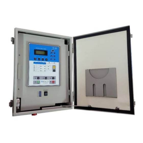
Page 96: Appendix 1. Drawings
Appendix 1. Drawings 1) Enclosure (Control Cabinet) - Page 97 Load Break Switch Control ERT-200S...
Need help?
Do you have a question about the ERT-200S and is the answer not in the manual?
Questions and answers